
1999 S10 2.2L Fuse Box Quesion. There are two (what appear
The fuse box in the 1999 S10 2.2L vehicle serves as a critical distribution point for electrical power to various components. The two main power terminals located at the top left and right are essential for understanding the vehicle's electrical architecture. The full-time power terminal typically provides constant voltage, while the RUN power terminal is activated when the ignition switch is in the ON position. Proper identification of these terminals is crucial for restoring functionality to the vehicle.
During reassembly, the underhood fuse block must be securely connected to its support bracket, with electrical connectors tightened to specified torque values of 7 N·m (62 lb·in). The battery positive cable connection to the underhood fuse block should be tightened to 10 N·m (89 lb·in). These connections ensure that the necessary voltage is supplied to the various circuits.
The absence of power at the interior fuse panel connector indicates a potential issue with the wiring or connections leading to the main Fuse/Relay box. The engine cranking without starting suggests that while some circuits are receiving power, critical circuits such as the fuel pump and instrument panel are not. The power distribution to the instrument panel fuse box is facilitated through heavy gauge feeder wires, typically color-coded as red, orange, blue, and purple. The lack of voltage at these terminals, regardless of the ignition switch position, necessitates a thorough examination of the wiring and connections.
The ignition switch is integral to the operation of several systems, including the instrument panel and fuel pump. The ignition B fuse, which feeds the ignition switch, must have voltage on both sides to allow power to flow through the Red and White wires to the ignition switch circuit. If the IGN B 50 amp fuse is operational, the Orange wire circuit must also be checked for continuity to ensure power is supplied to the instrument panel fuse box.
Additionally, the instrument cluster receives power through the ignition switch via the White circuit and Pink circuit, which are connected to the IGN A 40 amp fuse. If there is no power at the IGN A fuse, further investigation is warranted to locate the missing B+ connection, potentially at the buss bar stud.
To resolve the power issues, a systematic approach is recommended, focusing on one circuit at a time. Voltage measurements should be taken at various points in the circuit to identify where power is lost. This methodical tracing of the wiring will aid in isolating the problem and restoring functionality to the vehicle's electrical system.1999 S10 2. 2L Fuse Box Quesion. There are two (what appear to be) main power terminals on the top left and top right on the Fuse Box. Which terminal is the full time power terminal and which is the RUN power terminal Vehicle was a basket case and I am re-assembling the vehicle including re-installing the Fuse Box and harnesses, dashboard, etc, whi
ch were removed by another party. I have no power at the Interior Fuse panel connector which connects to the main Fuse/Relay box in engine compartment. Connect the electrical connectors to the underhood fuse block. Tighten Tighten the electrical connector to the underhood fuse block bolts to 7 N. m (62 lb in). Install the bolts that attach the underhood fuse block to the underhood fuse block support bracket. Tighten Tighten the underhood fuse block to the underhood fuse block support bracket bolts to 7 N. m (62 lb in). Attach the battery positive cable with bolt to the underhood fuse block. Tighten Tighten the battery positive cable to the underhood fuse block bolt to 10 N. m (89 lb in). Perhaps I phrased the question incorrectly, or did not describe my problem correctly. Through intuition, I managed to get everything plugged together with respect to the harnesses, and connected the engine fuse box to battery power, as shown on the diagrams.
The engine cranks, etc, but I have no power to the fuel pump, instrument panel, and no power on the instrument panel fuse box. I thought I was missing another major B+ connection on the Engine compartment fuse box. (What is the terminal on the upper right hand side of this fuse box ) The instrument panel fuse box appears to be fed power through a heavy power connector (red, orange, blue, and purple wires).
There is no power on any of these terminals with the key turned on (or off!). I have your same or similar wiring diagrams from Autozone`s site as well as from my 1999 S10 Haynes Manual (Haynes=vague) Perhaps I need wiring diagrams of the harnesses The 4 red, orange, blue, purple feeder wires to the instrument fuse box are not identified on any of the above diagrams, that I can find. I will happily pay you more for additional help. You have helped a lot so far, but the engine still will not start without ignition and fuel pump power.
Looks like the IP fuse panel picks up power through the Orange wire directly through the Ignition switch. The Ignition B Fuse feeds the the Ignition Switch through the Red and White. If the IGN B 50 amp fuse has power on both sides, then your Red and then Red and White to the Ignition switch circuit 342 needs to have 12 volts in order for the IP fuses shown above to have power.
So that Orange wire circuit 300 needs to have power for this portion of the IP fuse box to have power. Now your Instrument Cluster also picks up power through the Ignition Switch Via the White circuit 1390 and Pink Circuit 3 from the switch to the IP fuse block.
That come to the switch from the IGN A Fuse 40 amp. If you have no power getting to the 40 amp IGN A fuse, let`s look at that too. I`m searching for the other post you are referencing. That may be the B+ buss bar stud that is missing a connection if the IGN A fuse does not have power getting to it. We may need to focus on just one of the circuits that is not being powered. and backtrace to the power source. This may solve everything. I apologize that this is taking so long to isolate. Thanks for your quick reply. Like I said, though, when I unplug the heavy power lead going to the ip fuse panel, and check it with a VOM, there is no power on any of the leads withe the ign sw in any position.
I will look forward to your reply. Thanks Much! Let`s just take that IP fuse panel, and let`s determine at which point there should be power where there is no power, and we`ll determine the problem with just that circuit. We need to look closely at a wiring diagram I sent you earlier. I will ask you to check for voltage at a couple of 🔗 External reference
Related Circuits
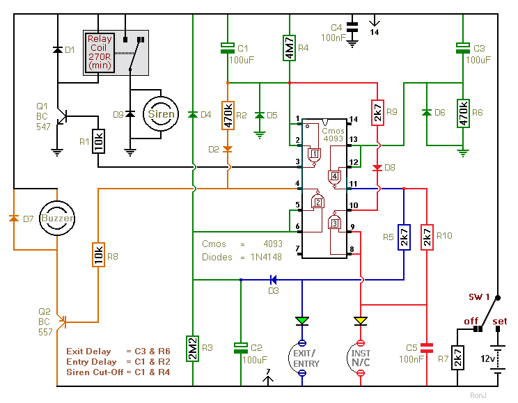
This is a two-zone alarm system featuring automatic exit, entry, and siren cut-off timers. It can be activated by standard normally-closed input devices such as magnetic reed contacts, foil tape, and passive infrared sensors (PIRs). The circuit is designed...
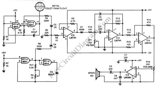
This schematic diagram illustrates a single-chip Theremin circuit. A Theremin is an electronic musical instrument that detects hand movements to control tones and frequency. The circuit employs two separate Colpitts LC oscillators to generate a beat frequency. The frequencies...
This circuit is designed for children's entertainment and is appropriate for installation on bicycles, battery-powered cars, motorcycles, as well as in models and other games. The circuit functions as a playful accessory that enhances the experience of riding or playing...
This indicator shows through a dual-LED see if a fuse is intact. The module is designed for 230 V AC. The green LED illuminates when the fuse is still good, the red lights when the fuse is broken. Perhaps...
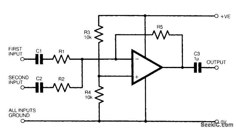
The figure illustrates a fundamental two-channel operational amplifier (op-amp) mixer circuit. The gain for channel 1 is determined by the ratio of resistors R5 to R1, while for channel 2, it is determined by the ratio of R5 to...
In situations where temperature measurement is required in a remote area, an imaging unit is installed, necessitating a connection to the appropriate sensor. The most commonly used cables typically consist of three conductors: two for powering the sensor and...