
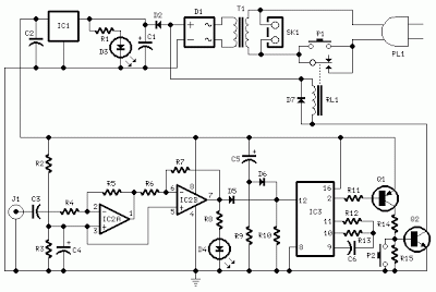
1KHz IR transmitter circuit

The described circuit operates effectively as a low-power infrared transmitter, leveraging the NE555 timer's versatility to generate a stable 1 kHz pulse train. The astable multivibrator configuration allows for continuous oscillation, producing square waves that can be efficiently amplified. The choice of the SK100 transistor for amplification is appropriate due to its capability to handle the current required to drive the IR LEDs, ensuring that the emitted IR light is sufficient for remote control applications.
The resistors R1 and R2, along with capacitor C2, are critical in determining the frequency of oscillation. The values of these components can be calculated using the standard formula for the frequency of an astable multivibrator:
\[ f = \frac{1.44}{(R1 + 2R2) \cdot C2} \]
Where \( f \) is the frequency in hertz, \( R1 \) and \( R2 \) are in ohms, and \( C2 \) is in farads. Adjusting these components allows for fine-tuning of the output frequency to meet specific application requirements.
The circuit's operation is initiated by the push-button switch S1. When pressed, S1 completes the circuit, allowing current to flow and activating the NE555 timer. This results in the generation of IR pulses that can be used for various remote control functions, such as operating electronic devices or controlling systems from a distance.
Overall, the design is straightforward and can be implemented with commonly available electronic components, making it accessible for hobbyists and professionals alike. The effective range of approximately 10 meters makes it suitable for many practical applications, while the simplicity of the circuit allows for easy troubleshooting and modifications.This circuit was designed in response to a request from my reader. What he asked for was a 1KHz IR transmitter circuit for some remote control application. I think this circuit may satisfy him. Any way this circuit can be used where ever a low power IR transmitter of 1 KHz operating frequency is needed. This transmitter can transmit up to a distan ce of about 10 meters. The circuit is based on a NE555 timer IC (IC1) which is wires as an astable multivibrator to produce 1KHz pulses. The output pulses of the IC1 will be amplified by the Q1(SK100) to drive the two IR transmitter LEDs wired serially.
The resistors R1, R2 and capacitor C2 determines the operating frequency of the IC. The circuit starts emitting IR pulses when ever the push button switch S1 is pressed. 🔗 External reference
Related Circuits
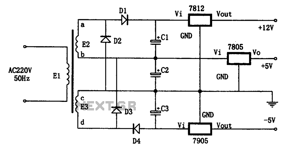
The circuit illustrated in the figure represents a specialized power supply configuration. It is straightforward in design and can be constructed using two identical secondary windings to generate three distinct DC voltage outputs: +5V, -5V, and +12V. The circuit...
The mixer features two stereo phono inputs and two stereo line-level inputs, along with one stereo bonded channel. It also includes a microphone input and a stereo output with adjustable gain. The mixer is designed to accommodate a variety of...
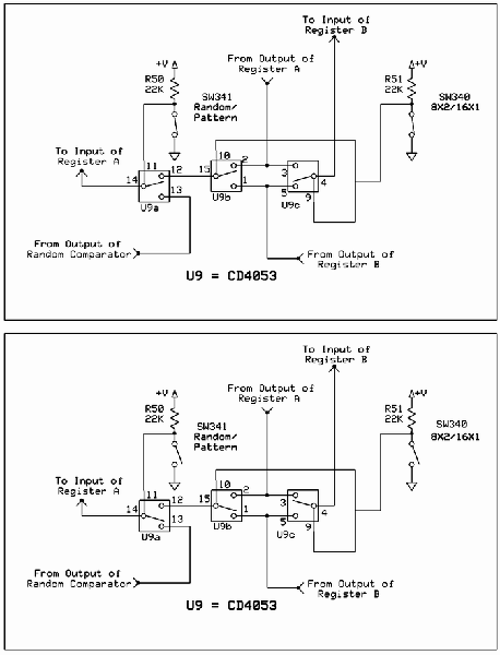
The circuit involves Clock and Load functions, with the Load function being described first. The component U5, a CD4013, is responsible for executing the load function by determining whether the shift register integrated circuits (ICs) operate in parallel or...
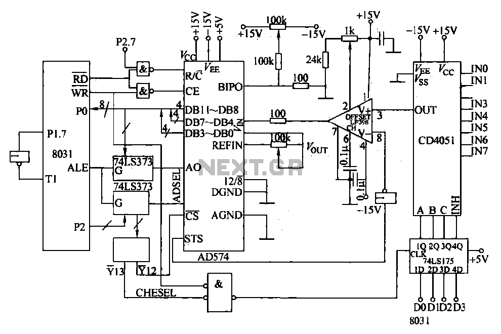
Converters and data sampling: A 12-bit A/D converter, AD574, is interfaced with an 8031 microcontroller circuit. Parameters are measured by a multi-way switch after a CD4051 strobe signal is sent to the sample/hold input device. The selection of the...
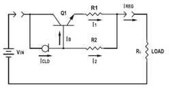
This application datasheet article includes sections that discuss the practical current booster circuit technique, which involves a conventional circuit using a Constant Current Load (CLD) and a current boosting circuit technique. It covers the analysis of the booster circuit...
This is a single-zone alarm system featuring automatic exit, entry, and siren cut-off timers. It is designed to accommodate various types of normally-closed input devices, including magnetic reed contacts, foil tape, and passive infrared sensors (PIRs). Additionally, it is...