
Special power circuits 7905 7805 7812

This power supply circuit utilizes a transformer with dual secondary windings, which allows for the simultaneous generation of multiple voltage levels. The two secondary windings are configured to provide the necessary AC input for the rectification process. The diodes D2 and D3 are essential components, as they rectify the alternating current (AC) from the secondary windings into direct current (DC).
The full-wave rectification achieved by these diodes ensures that both halves of the AC waveform are utilized, resulting in a smoother DC output. The output voltages are +5V, -5V, and +12V, which can be used for various electronic applications requiring dual polarity and higher voltage.
Filtering capacitors may be employed at the output of the rectifiers to further smooth the DC voltage levels, reducing ripple and improving the overall stability of the power supply. The design's simplicity makes it suitable for applications where space and cost are critical factors. This power supply circuit can be effectively used in low-power electronic devices, instrumentation, and other applications that require reliable voltage regulation. As shown in FIG as a special power supply circuit. The circuit is simple, but can be produced from two identical secondary windings in three sets DC voltage: + 5V, -5V and + 12 V. Its characteristics are: D2, D3 connected across E2, E3 which two AC power, plays the role of the full-wave rectification.
Related Circuits
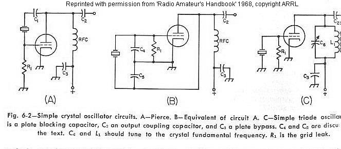
The frequency of a crystal-controlled oscillator is maintained with high precision through the use of a quartz crystal. The frequency is primarily determined by the dimensions of the crystal, particularly its thickness, while other circuit parameters have minimal impact....
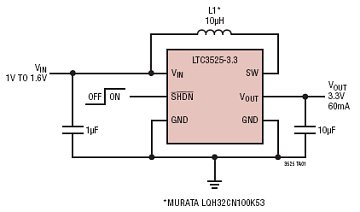
The LTC3525-3/LTC3525-3.3/LTC3525-5 are high-efficiency synchronous step-up DC/DC converters with output disconnect capability that can operate with an input voltage as low as 1V. These converters provide a compact and efficient alternative to charge pumps for single-cell or dual-cell alkaline...
A good way to mount the circuit board is to use a hot glue gun to mold the circuit underneath the lamp housing. There is plenty of space there for your board. At the next photos you can see...
This converter features a central component, the CMOS 4047, which converts a 12V DC voltage into a 220V AC voltage. The 4047 operates as an astable multivibrator. At pins 10 and 11, a symmetrical rectangular signal is generated, which...
The following circuit illustrates a Power Amplifier Circuit Diagram utilizing a 2N3055 transistor. Features include a 500-ohm current and an optimal voltage of 50V. The power amplifier circuit based on the 2N3055 transistor is designed to deliver significant output power,...
This circuit is designed for individuals needing to boost or drop a voltage. The output operates at high frequency but can be rectified and filtered to provide a DC output. When rectifying high frequencies, it is essential to utilize...