
1W LED Driver
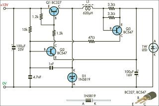
The circuit utilizes a constant current driver configuration to ensure that the LEDs operate efficiently while maintaining their rated performance. The primary components of this circuit include a power supply, a current sensing resistor, and a feedback mechanism to regulate the output current.
The power supply provides the necessary voltage to the circuit, which is typically higher than the forward voltage of the LED to ensure proper operation. The current sensing resistor is placed in series with the LED, allowing the circuit to monitor the current flowing through the LED. By measuring the voltage drop across this resistor, the circuit can determine the actual current flowing through the LED.
A feedback loop is implemented using an operational amplifier or a dedicated LED driver IC. This feedback mechanism adjusts the output voltage to maintain a constant current, compensating for variations in the LED's forward voltage due to temperature changes or manufacturing tolerances.
To enhance thermal management, appropriate heat sinking should be considered, as 1W LEDs can generate significant heat during operation. Additionally, the circuit may include protective features such as overcurrent protection, thermal shutdown, and reverse polarity protection to ensure the longevity and reliability of the LEDs.
Overall, this circuit design effectively addresses the unique characteristics of 1W LEDs, providing a reliable and efficient solution for various lighting applications.This circuit is designed to drive the 1W LEDs that are now commonly available. Their non-linear voltage to current relationship and variation in forward v.. 🔗 External reference
Related Circuits

This circuit utilizes small switching transistors, with a maximum motor drive current limited to approximately 250 mA at 5V. Testing has been conducted across a voltage range from 3V to 21V, and with certain component modifications, it may be...

This circuit was designed as a warning flasher to alert road users to dangerous situations in the dark. Alternatively, it can act as a bicycle light. The circuit operates by utilizing a light-emitting diode (LED) as the primary visual alerting...

In this project it was used the Piranha Super-flux RGB Led of common anode, and the PIC18F25K20, in order to generate combinations of colors. It has two function modes, automatic that generate the color sequence that is stored in...
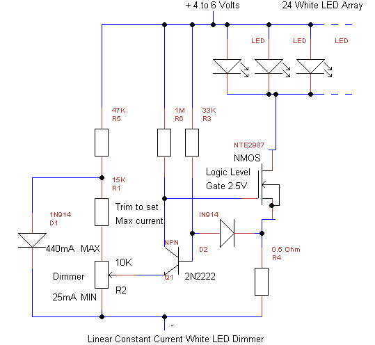
This simple linear circuit provides continuously variable regulated current (~25-400mA) from a 4-6 Volt source. The linear design is chosen for simplicity, reliability, ease of repair, and to avoid switching EMI in cave radios. The circuit requires only 0.2V...

An efficient automatic solar garden lights circuit with minimal components. The advantage is that it operates entirely autonomously, with the solar panel functioning as a light detector. It switches the lamp off at dawn, charges the battery during the...

The drive circuits for unipolar stepper motors are typically straightforward. In their simplest configuration, a transistor or MOSFET is employed to control each section of the windings. The control signal must be supplied programmatically to the four windings of...
Warning: include(partials/cookie-banner.php): Failed to open stream: Permission denied in /var/www/html/nextgr/view-circuit.php on line 713
Warning: include(): Failed opening 'partials/cookie-banner.php' for inclusion (include_path='.:/usr/share/php') in /var/www/html/nextgr/view-circuit.php on line 713