
Digitally controlled threshold detector

The circuit described is a sophisticated solar tracking system that integrates various electronic components to enhance performance and reliability. The use of small switching transistors ensures efficient control of motor drive currents, while the potential for operation at higher voltages allows for flexibility in different solar panel configurations. The implementation of a Schmitt trigger hex inverter circuit effectively addresses issues of relay chatter, which can compromise the functionality of the system under variable lighting conditions.
Incorporating LEDs as voltage-generating sensors represents an innovative approach to solar tracking, leveraging the unique properties of Gallium Phosphide to achieve higher voltage outputs compared to traditional silicon PV cells. This method not only improves sensitivity but also provides a cost-effective solution for solar tracking applications. The design allows for precise calibration, enabling the system to adjust its orientation effectively in response to sunlight.
The inclusion of limit switches is a critical safety feature that prevents mechanical overloads by ensuring that motor movement is halted before reaching physical constraints. The diagram illustrating the operation of these switches provides a clear understanding of their role in the circuit, emphasizing the importance of selecting appropriate components to handle the expected electrical loads.
Overall, this circuit exemplifies the integration of advanced electronic principles to create a functional and efficient solar tracking system, demonstrating potential for both commercial and experimental applications in renewable energy technologies.This circuit uses small switching transistors. The maximum motor drive current is limited to about 250mA maximum at 5V. I`ve tested the circuit on voltages from 3V to 21V. With some component changes it should be usefulto 63V in a 36V PV panel system although I haven`t tried this yet. With higher voltage and the use of heat sinks on the bridge transistors much higher currents should be possible.
(View) Circuit 1 tends to chatter the relays under certain lighting conditions as there is no built in hysteresis. This version uses a Schmitt trigger hex inverter circuit to eliminate the chatter. It works better but is more complex. Note! R4 and R5 are used to force parking when it gets dark. If parking is not desired don`t use R4 and R5. Parking may not be desired in low power consumption applications. Also, the parking resistors, R4 and R5, reduce sensitivity a bit. (View) I have been looking for truly low cost and yet accurate conventional solar trackers. The CdS tracker is pretty good but lacks accuracy and sensitivity. I was thinking about using PV cells as the sensor. I was experimenting with LEDs and noticed they generate voltage in sunlight. Bingo! This got me to thinking. They generate quite a bit of voltage. The green ones generate about 1. 65V, some as much a 1. 74V. Not the piddley. 55 volts of a silicon PV cell. How is this so Well, it turns out green LEDs are made from Gallium Phosphide, a semiconductor with a much higher bandgap voltage.
I thought I had invented the use of LEDs as PV cells as I had never heard of this effect before. Well, after some investigating I found a number of references to this. The guys that had done the most work in this area were the people form the BEAM project. They make tiny solar powered robots and some used LED photo sensors. I had been using a very low threshold MOSFET in a TO-92 package, BS107PT. The threshold is about 1. 5V. If I put two LEDs back to back, one fighting the other, the one with more light intensity wins. I thought I could use this to switch the MOSFET. And it worked. By using one LED as a sort of power supply and the back to back pair connected from it to the MOSFET gate the circuit is complete. (This I have not seen elsewhere. ) My implementation uses three power supply LEDs, aimed East, Up, and West. The sensor LEDs are aimed about 90 °s from each other and at about 45 °s either side of up. Of course the easterly pair will be a little to the East and the westerly pair a little to the West. This makes the center have a dead zone where tracking stops. The circuit is quite sensitive. It brings the panel back to the East just after sun rise. The accuracy is quite good. You can calibrate the sensor by bending or aiming the LEDs a bit. While the proof of concept is good it will burn the relay contacts, similar to that on the Cadmium Sulfide tracker.
This is caused by the relays being turned on or off slowly. It melted the plastic case on the relays. (View) Limit switches are essential for servo motor operation with solar trackers. I made this diagram to help explain how they work. Top. Normal operation between limit switches. Middle. The left limit switch has opened to stop movement to the left. To move to the right again the diode conducts current that allows movement to the right. Bottom. The right limit switch has opened to stop movement to the right. To move to the left again the diode conducts current that allows movement to the left. Sellect a diode or rectifier rated at the maximum motor current plus some margine. Also the voltage should be at leat 100V and preferably 200V. Needles to say, the limit switch must operate before the mechanical limits are reached. If the mechanical stop is reached before the switch the motor can draw quite high currents and can destroy the solar t 🔗 External reference
Related Circuits
Most metal detectors operate on the principle that metals within a magnetic field alter the behavior of that field. There are two primary methods for detecting these changes. In one method, an alternating current is supplied to a transmit...

This single-chip circuit adjusts its audio gain according to the ambient noise picked up by the microphone. When operating in a quiet environment, the audio output is quiet, while a noisy environment results in a louder audio output. Audio...
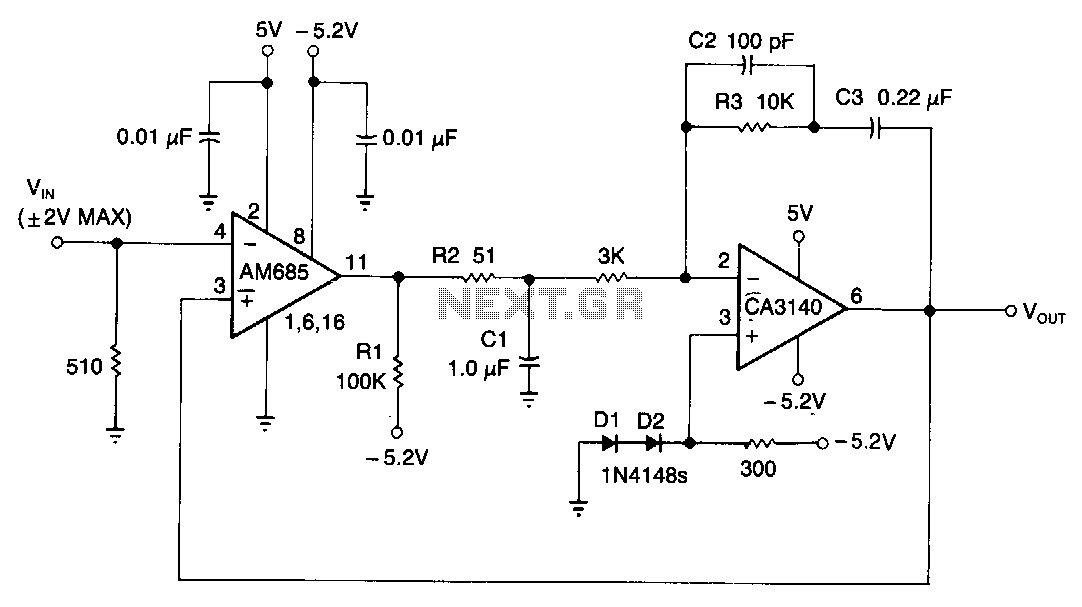
This circuit is capable of detecting positive peaks for signal frequencies exceeding 5 MHz, achieving an accuracy of ±1% for signal amplitudes ranging from 400 mV to 4 V peak-to-peak across sine, square, and triangular waveforms. The AM685 comparator...
This is a straightforward infrared detector circuit designed to detect infrared light. The circuit comprises only three components: an RS-276-145 photo transistor, a 330-ohm resistor, and a general-purpose LED (Light Emitting Diode). When the photo transistor receives infrared light...
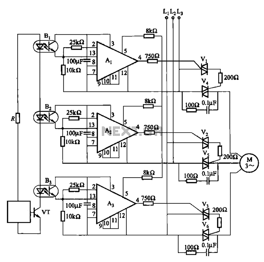
The 331 circuit depicted in the figure utilizes a two-way thyristor for controlling the start and stop functions of a motor. It operates without mechanical contacts, generating no noise or sparks, making it suitable for applications that require frequent...
This simple circuit can be used to activate various devices, such as microcontrollers, relays, secret alarms, or even to turn on LED1, which illuminates as long as a metal plate is touched. The circuit consists of a voltage divider...