
2-5-cell lithium battery charger circuit

The universal rechargeable lithium battery circuit is engineered to accommodate various lithium battery types, providing flexibility in both the number of cells used and their specific characteristics. The circuit's design allows for the adjustment of the charger output voltage and current limit setpoint, which is crucial for optimizing charging conditions tailored to the specific battery chemistry and configuration.
At the heart of this design is a voltage regulation mechanism that ensures the output voltage remains within the safe operating limits of the lithium batteries, preventing overcharging and potential damage. This is achieved through a combination of operational amplifiers and feedback loops that monitor the charging voltage and adjust it according to the selected resistor values.
The current limit feature is equally important, as it prevents excessive current from flowing into the batteries during the charging process. By varying the resistance in the circuit, the maximum charging current can be set to match the specifications of the connected battery. This adaptability makes the circuit suitable for a wide array of applications, from small consumer electronics to larger battery banks used in renewable energy systems.
Additionally, safety features such as thermal protection and short-circuit prevention can be integrated into the design, further enhancing the reliability of the charger. The inclusion of LED indicators can provide visual feedback on the charging status, indicating when the batteries are fully charged or if there are any issues during the charging process.
Overall, the universal rechargeable lithium battery circuit design offers a versatile and efficient solution for charging various lithium battery types, with adjustable parameters that ensure optimal performance and safety.A universal rechargeable lithium battery circuit design, applicable to different battery types and number of batteries. This is because both the charger output voltage or curre nt limit setpoint or the maximum charging current can be adjusted by simply changing the resistor.
Related Circuits
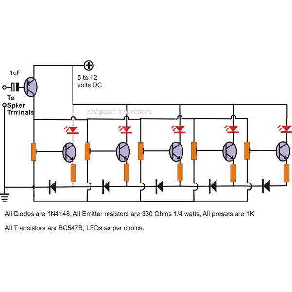
The LEDs in the circuit light up sequentially and "dance" in response to the music level applied at the input, preferably from the speaker terminals of the audio device being monitored. This configuration is consistent across all LEDs in...
This article presents a driver circuit for a 12V, 5W fluorescent lamp. The circuit utilizes a standard 220V to 10V step-down transformer operated in reverse to achieve a 12V output. The driver circuit for a 12V, 5W fluorescent lamp is...
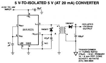
A negative output voltage DC to DC converter generates a -5V output at pin A. To achieve -5V at point A, the primary of the transformer must fly back to a diode drop more negative than -5V. If the...
This circuit is a difference amplifier. It functions as an inverting amplifier that enables the subtraction of two voltages, effectively performing a summation. The difference amplifier is a fundamental circuit configuration in analog electronics, primarily used for amplifying the difference...
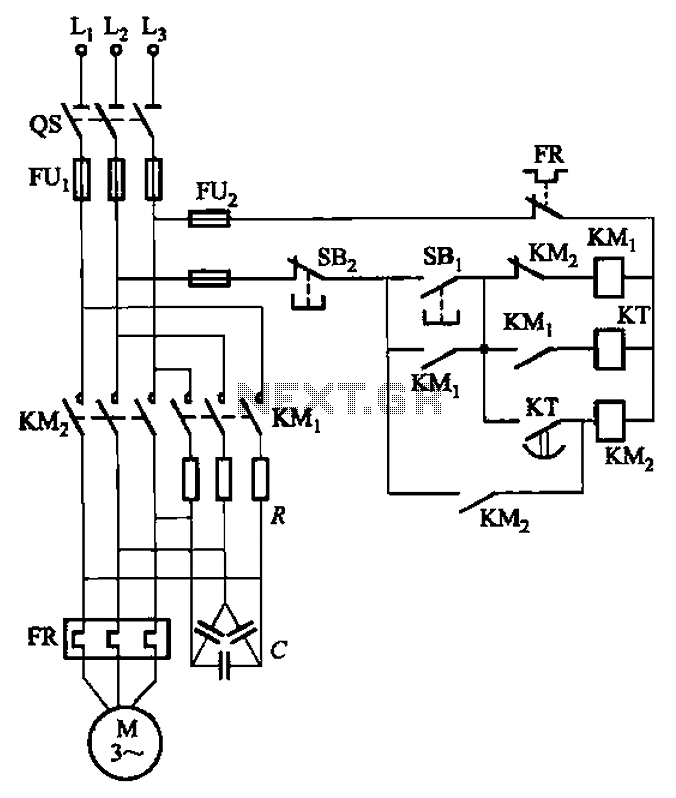
The circuit depicted in Figure 3-35 demonstrates a method for starting a motor that transitions to full voltage through a step-down switching process. This approach provides an uninterruptible power supply, effectively preventing issues related to switching currents that may...
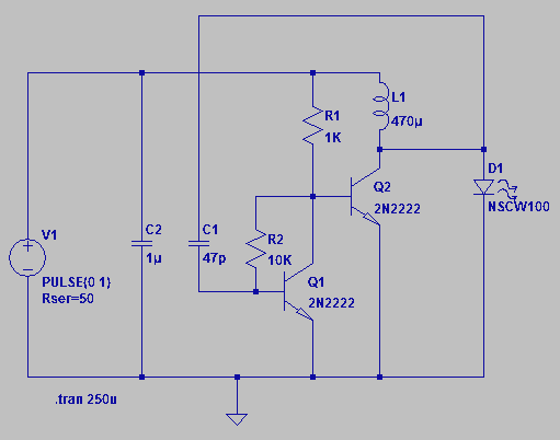
Four observations regarding the Joule Thief AA battery LED circuit. The schematic of the LED circuit illustrates the power source (V1), which symbolizes a depleted battery with only 1 volt remaining and an internal resistance. The Joule Thief circuit is...