
2 -Y- connection automatic three-speed motor acceleration control circuit

The automatic acceleration control circuit depicted in Figure 3-118 is designed to enhance motor performance by providing a controlled ramp-up in speed. The primary component, a male contactor time relay, plays a crucial role in managing the motor's startup sequence. Upon activation, the time relay initiates the motor at a predetermined low speed, allowing for a gradual increase in speed to high operational levels.
The circuit typically consists of the following components: a power supply, the male contactor time relay, a motor, and various control elements such as switches and resistors. The power supply provides the necessary voltage and current to the motor and relay. The male contactor time relay is configured to close its contacts after a specific delay, which is adjustable based on the application requirements. This delay ensures that the motor does not start at full speed immediately, thus preventing mechanical stress and potential damage.
In operation, when the circuit is powered, the relay remains open for a set duration, during which the motor operates at low speed. After the elapsed time, the relay closes, allowing the motor to transition smoothly to high-speed operation. This method not only improves the reliability and longevity of the motor but also enhances overall system efficiency.
In addition to the relay, the circuit may incorporate safety features such as overload protection and thermal sensors to monitor motor temperature. These elements ensure that the motor operates within safe parameters, further contributing to its durability and performance. The design can be tailored to various motor types and applications, making it a versatile solution for automatic acceleration control in industrial and commercial settings.Figure 3-118 automatic acceleration control circuit. It uses the male contactor time relay, the motor starts automatically from a low speed by the speed the transition to high- speed operation.
Related Circuits
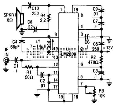
An LM2808 performs IF amplification of the 4.5-MHz sound subcarrier, limiting, detection, and audio amplification. If the center frequency must be changed, then change L1/C4. Audio output is 0.5 W. R3 is the volume control. The LM2808 is an integrated...
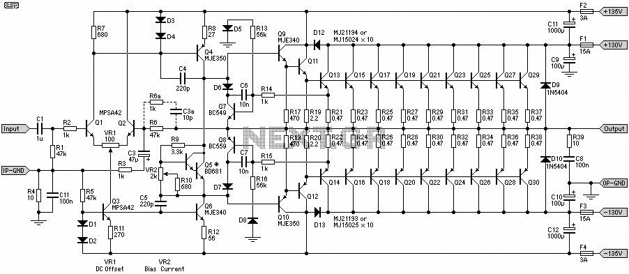
This 1500W Power Amplifier Circuit Diagram contains two images of the circuit. For more complete information, refer to the main post titled "1500 Watt Power Amplifier." It includes a list of component parts for the 1500W Power Amplifier Circuit...
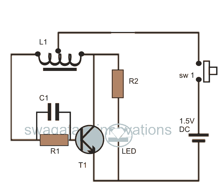
This post discusses blue and white LED drivers utilizing a joule thief circuit. Further exploration of the circuit's functionality is provided, along with simulation points. The joule thief circuit is a simple and efficient boost converter that allows for the...
Just point this small device at the TV and the remote gets jammed. The circuit is self-explanatory. 555 is wired as an astable multivibrator for a frequency of nearly 38 kHz. This is the frequency at which most of...
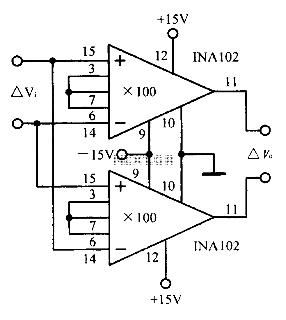
A differential input differential output amplifying circuit diagram. A differential input differential output (DIDO) amplifier is a type of operational amplifier configuration that is designed to amplify the difference between two input signals while rejecting any signals that are common...
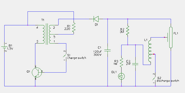
This document provides a step-by-step guide for modifying a disposable camera flash unit to serve as a power supply for a Geiger tube. The process involves removing the flash tube and trigger transformer from the circuit board by gently...