
Blue White LED Driver Circuit Joule Thief

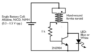
The joule thief circuit is a simple and efficient boost converter that allows for the operation of LEDs at low input voltages, such as those from depleted batteries. It operates on the principle of energy storage and transfer, utilizing an inductor to step up the voltage to a level suitable for powering blue and white LEDs, which typically require higher forward voltages than standard red or green LEDs.
The circuit typically consists of a few key components: a transistor, an inductor, a resistor, and two diodes. The transistor is used to switch the current through the inductor on and off, creating a magnetic field. When the transistor is turned off, the magnetic field collapses, inducing a voltage across the inductor that is higher than the input voltage. This induced voltage is then used to drive the LEDs.
For simulation purposes, the parameters of the circuit can be adjusted to observe the effects on LED brightness and efficiency. Key simulation points include the input voltage range, the type and value of the inductor, the switching frequency of the transistor, and the load resistance represented by the LEDs. It is essential to ensure that the transistor is appropriately rated for the current and voltage levels in the circuit to avoid damage.
The joule thief circuit's simplicity and effectiveness make it an excellent choice for applications where maximizing battery life is critical, such as in portable or low-power devices. By understanding the operation and characteristics of this circuit, designers can create efficient LED drivers that extend the usability of energy sources.Blue and white LED drivers using joule thief circuit has been covered in this post, lets learn more. The circuit may be simulated with the following points 🔗 External reference
Related Circuits
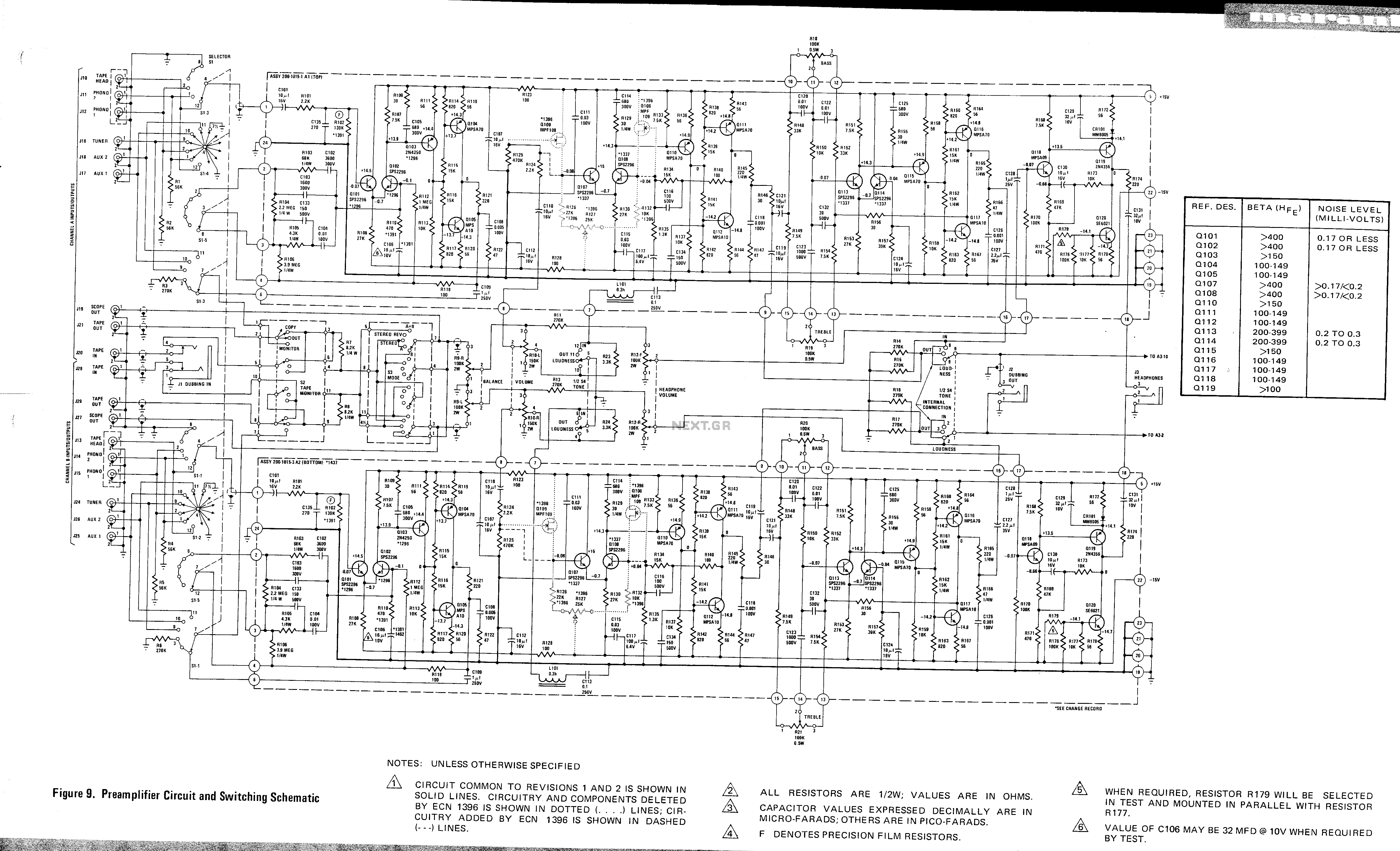
This is a preamplifier circuit and switching schematic for the Marantz Model 33. The Marantz Model 33 preamplifier circuit is designed to amplify low-level audio signals from various sources before sending them to a power amplifier. The schematic typically includes...
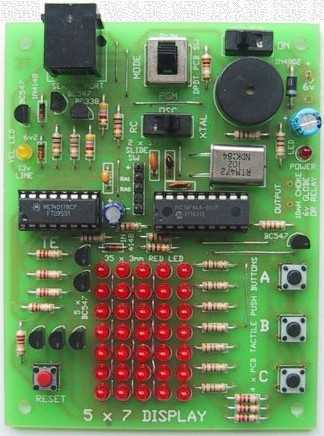
Your 5x7 display is my favourite toy; the tunes and graphics in the elevator display always impress my mates! Since building the display I developed my own 400 dot matrix using a pic and the SN74154 4bit binary to...

The schematic for this project is deceptively simple compared to the complexity of the circuit's operation. The two signals generated are mixed together at the base of transistor T2, and once it exits the collector of the transistor, the...
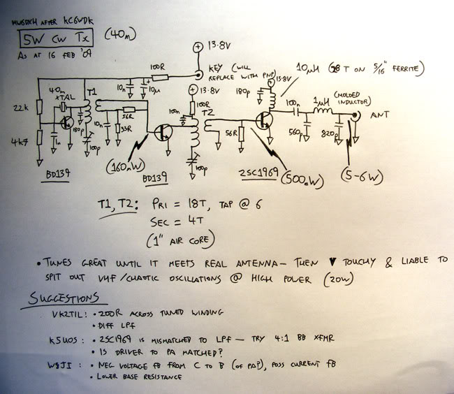
A newly licensed individual is engaging in traditional methods of amateur radio, focusing on continuous wave (CW) communication and homebrewing. They have constructed several basic receivers, an antenna matcher, a standing wave ratio (SWR) meter, a PC-rig interface, and...
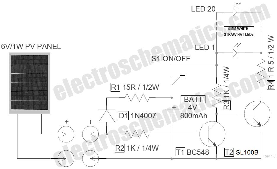
The circuit for the LED solar lantern lights is designed using a 6V/1W solar panel (photovoltaic panel) and a 4V/800mAh lead-acid battery. The schematic for the LED solar lantern circuit incorporates a solar panel that converts sunlight into electrical energy....
Tired of experimenting with capacitors? It's time to explore supercapacitors, which offer significant storage capabilities. This article provides instructions on building a small LED flashlight utilizing supercapacitors. A minimum voltage of 2 volts is necessary to illuminate the LED,...