
20 electrical documentation schematics

The electronic schematic referenced in the above description likely involves fundamental components and power connections, which are critical in understanding circuit design and functionality. The schematic may include basic electronic elements such as resistors, capacitors, diodes, and transistors, each playing a specific role in circuit operation. Resistors are used to limit current flow, capacitors store and release electrical energy, diodes allow current to flow in one direction while blocking it in the opposite direction, and transistors serve as switches or amplifiers.
In the context of power and connections, the schematic may illustrate how these components are interconnected to form a complete circuit. Power sources, such as batteries or power supplies, are typically represented, showing how voltage is supplied to the circuit. Connections between components are often depicted with lines indicating the flow of electricity, and nodes where components meet are critical for understanding how signals propagate through the circuit.
Students are expected to analyze the schematic, identify components, and understand their functions within the circuit. This exercise will enhance their ability to interpret and design electronic circuits, laying the groundwork for more advanced topics in electronics and engineering.NOTE - THE DUE DATES FOR LECTURES 20-25 WILL BE MOVED TO WEDNESDAY AT 1:00PM Download the Notes TOPIC 1: Basic components (Listen to Dr. Stienecker) TOPIC 2: Power and Connections (Listen to Dr. Stieneker) You should now be prepared to answer the following questions based on the pictured schematic. Click here to find the.
🔗 External reference
Related Circuits
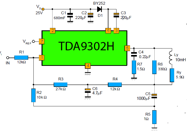
The TDA9302H is a monolithic integrated circuit housed in a HEPTAWATTTM package. It functions as a high-efficiency power amplifier designed for direct drive vertical deflection coils in television yokes. This component is suitable for use in both color and...
The Dynaco Mark III is the highest power amplifier that was widely sold under the Dynaco name. There was a higher power amp (the Mark VI), but it wasn't widely available. The Dyna MKIII has a basic design flaw...
This simple circuit employs a 741 operational amplifier (op-amp) in differential mode to function as a continuity tester. The voltage difference between the non-inverting and inverting inputs is amplified by the full open-loop gain of the op-amp. Initially, ignore...

The provided connections will enable configuration-free usage for most Arduino boards. Some Arduino boards, such as the Mega2560, may require custom configuration due to how the ports on the Atmel AVR microcontroller are mapped to the digital pins on...
PIC C Compilers are utilized to compile source code, leveraging the extensive built-in functions offered by these compilers. A single C statement can produce multiple pages of PIC RISC instructions, eliminating the need for manual coding. CCS charges $125...
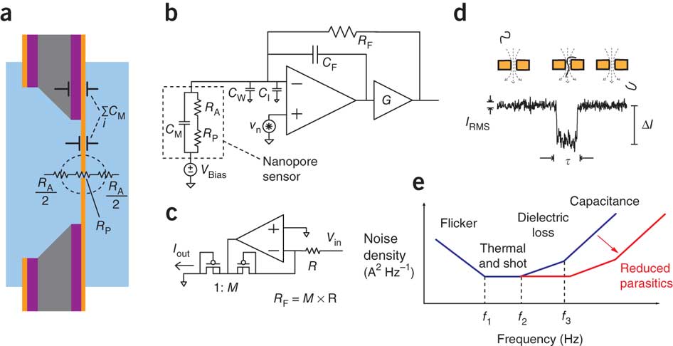
An illustration of the electronic impedances of a solid-state nanopore chip. A simplified circuit schematic of the voltage-clamp current preamplifier is provided. The circuit design of the low-noise current source substitutes for a feedback resistance (RF). An example transient...