
connection tester schematics

This circuit functions as a practical tool for testing continuity in electrical components. The 741 op-amp, configured in differential mode, allows for the detection of small voltage differences, which is critical for identifying open circuits or poor connections. The operational amplifier's high gain ensures that even minor discrepancies in resistance can be amplified to a level that activates the output indicator, in this case, LEDs.
The use of a resistor in the range of 0.22Ω to 4Ω serves to provide a reference point for the circuit. Adjusting the 10kΩ control allows the user to calibrate the sensitivity of the circuit, ensuring that the LEDs light up only when a valid connection is detected. This calibration step is essential for accurate testing, as it compensates for any minor variations in the op-amp's characteristics or the test environment.
The recommendation to maintain clean probes is paramount, as increased contact resistance can lead to false readings. This aspect is particularly important in practical applications where the circuit may be used in environments with dust or moisture, which can compromise performance.
The circuit's versatility is enhanced by its compatibility with various op-amps, including MOSFET and JFET types. This allows for flexibility in design, enabling the user to select an op-amp that meets specific application requirements or availability. The addition of a preset resistor across the offset null terminals provides a means to fine-tune the circuit, ensuring reliable operation under varying conditions.
Overall, this continuity tester circuit is a valuable tool for electronics professionals, providing a straightforward and effective means of verifying the integrity of electrical connections.This simple circuit uses a 741 op-amp in differential mode as a continuity tester. The voltage difference between the non-inverting and inverting inputs is amplified by the full open loop gain of the op-amp. Ignore the 470k and the 10k control for the moment, and look at the input of the op-amp. If the resistors were perfectly matched, then the vo ltage difference would be zero and output zero. However the use of the 470k and 10k control allows a small potential difference to be applied across the op-amp inputs and upset the balance of the circuit. This is amplified causing the op-amp output to swing to full supply voltage and light the LED`s. The probes should first be connected to a resistor of value between 0. 22 ohm and 4ohm. The control is adjusted until the LED`s just light with the resistance across the probes. The resistor should then be removed and probes short circuited, the LED`s should go out. As the low resistance value is extremely low, it is important that the probes, (whether crocodile clips or needles etc) be kept clean, otherwise dirt can increase contact resistance and cause the circuit to mis-operate.
The circuit should also work with a MOSFET type op-amp such as CA3130, CA3140, and JFET types, e. g. LF351. If the lED`s will not extinguish then a 10k preset should be wired across the offset null terminals, pins 1 and 5, the wiper of the control being connected to the negative battery terminal. 🔗 External reference
Related Circuits
This circuit utilizes the widely available LM3914 integrated circuit (IC). The LM3914 is straightforward to operate, does not require external voltage regulators due to its built-in voltage regulation, and can be powered by a variety of sources. The LM3914 is...
An FM tracer was developed using the LM3909 integrated circuit (IC) along with several supporting components. This 1.5V FM tracker serves as an indicator of revenue sources by emitting a signal through an LED. The FM tracking circuit operates...
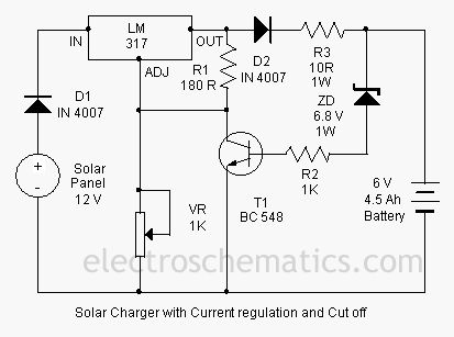
This is a solar charger circuit designed to charge Lead Acid or Ni-Cd batteries utilizing solar energy. The circuit captures solar energy to charge a 6-volt, 4.5 Ah rechargeable battery for various applications. It includes voltage and current regulation,...
This circuit utilizes the widely available LM3914 integrated circuit (IC). The LM3914 is straightforward to operate, does not require external voltage regulators due to its built-in voltage regulation, and can be powered from nearly any voltage source. This makes...

Gates G1 and G2, along with resistors R1 and R2, create a straightforward voltage monitor with a trip point set at 1 volt. Gate G3 functions as an inverter. The display section of the tester features a common anode...
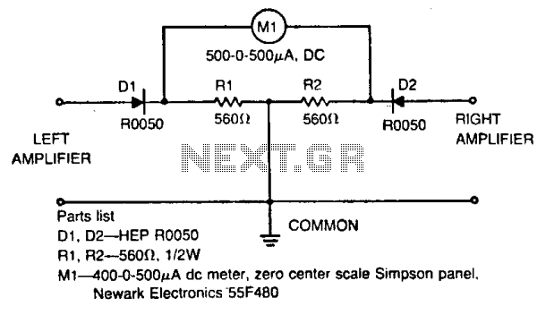
The meter displays the volume and tone control balance between the left and right stereo amplifiers. For enhanced usability, the meter is designed as a zero-center type. Resistors used in the circuit have a tolerance of five percent or...