
20 kHz ASTABLE

This single-capacitor circuit design is characterized by its robustness, making it suitable for applications requiring stable performance under varying environmental conditions. The circuit primarily utilizes a single capacitor, which simplifies the design while ensuring reliable operation across different temperatures and supply voltages.
The frequency stability of 0.05% across a voltage range of 6V to 12V indicates that the circuit is well-suited for applications where power supply variations are common. This feature is particularly beneficial in battery-operated devices where voltage levels may fluctuate as the battery discharges.
Timing in the circuit can be adjusted by varying the values of resistors R1 and R2, along with the capacitance of C. This flexibility allows for customization of the timing characteristics to meet specific application requirements. By selecting appropriate resistor and capacitor values, the designer can achieve the desired timing intervals, making this circuit versatile for different timing applications.
The duty cycle, which is defined as the ratio of the on-time to the total cycle time, is influenced by the resistors R3 and R4. A 50% duty cycle indicates that the output signal is high for half of the cycle duration, which is often desirable in applications such as pulse-width modulation (PWM) or clock signal generation. The ability to maintain this duty cycle with the specified resistor ratios enhances the circuit's functionality in various electronic applications.
Overall, this single-capacitor circuit design is an efficient solution for timing and frequency generation, providing reliable performance and ease of customization for a wide range of electronic applications.Single-capacitor circuit is reIiable over wide range of temperatures. voltages. and transistor gains. Frequency varies only by 0. 05% for supply voltage changes between 6 and 12 V. Timing can be changed with R1. R2. and C. Ducy cycle depends on ratio of R3. to R4. and is 50% forvaluesshown. -C. Horwitz, Tolerant Astable Circuits. Wireless World. Feb . 1975, p93. 🔗 External reference
Related Circuits

This circuit was first introduced by Signetics Corporation as the SE555/NE555 around 1971. Pin connections and functions are as follows: Pin 1 (Ground) is the most negative supply potential of the device, typically connected to circuit common when powered...
An astable multivibrator, also known as an oscillator circuit, operates on the principle of positive feedback. This type of circuit can be constructed using operational amplifiers, logic gates, or transistors. An astable multivibrator is a fundamental electronic circuit that generates...
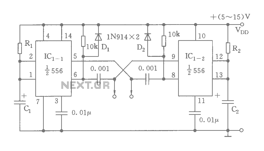
The circuit features a dual time base using a 556 timer, which comprises two synchronized multivibrators and two output clock signals. The output signals are synchronized with defined intervals, and the oscillation frequency can be adjusted by varying the...
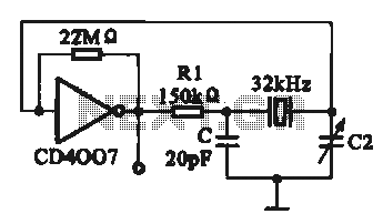
A 32 kHz clock oscillator is essential for digital circuits, as depicted in the schematic. The 32 kHz crystal clock oscillator serves to provide a time reference signal for the digital circuit. It utilizes a CMOS integrated circuit, specifically...
The small 8-pin PIC12C508 is pre-programmed to generate our 38KHz carrier frequency by simply pulsing I/O-pin GP1. The PIC will generate either 38KHz or 40KHz, depending on the state of GP3 when power is first applied. If you connect...
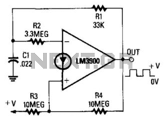
When the output is high, R3 and R4 are in parallel, and C1 charges through R1 until the current in R2 equals that at the non-inverting terminal. This action occurs when C1's voltage rises to 2/3 of the supply...