
20 kHz Astable Multivibrator with Transistors

An astable multivibrator is a fundamental electronic circuit that generates a continuous square wave output without requiring any external triggering. The circuit consists of two unstable states, oscillating between them, which results in a periodic output signal. The primary components involved in the design of an astable multivibrator include resistors, capacitors, and active devices such as operational amplifiers or transistors.
In the case of a transistor-based astable multivibrator, two NPN transistors can be configured in a feedback loop. The timing of the oscillation is determined by the values of the resistors and capacitors connected to the transistors. When the circuit is powered, one transistor turns on, causing the other to turn off, and vice versa. This switching action creates a square wave output at the collector of one of the transistors.
For an op-amp astable multivibrator, the configuration typically involves connecting the op-amp in a feedback loop with resistors and capacitors. The output oscillation frequency can be adjusted by changing the resistor and capacitor values, allowing for flexibility in design based on application requirements.
The output frequency (f) of the astable multivibrator can be calculated using the formula:
f = 1 / (ln(2) * (R1 + 2R2) * C)
where R1 and R2 are the resistances in ohms, and C is the capacitance in farads. This equation highlights the relationship between the timing components and the frequency of the output signal.
Astable multivibrators are widely used in various applications, including clock pulse generation, LED flashers, and tone generation in audio devices. The simplicity and versatility of the astable multivibrator make it a fundamental building block in electronic circuit design.Astable multivibrator or oscillator circuit is based on positive feedback. We can design such circuit using op-amp, logic gates, or transistors. Here we can. 🔗 External reference
Related Circuits
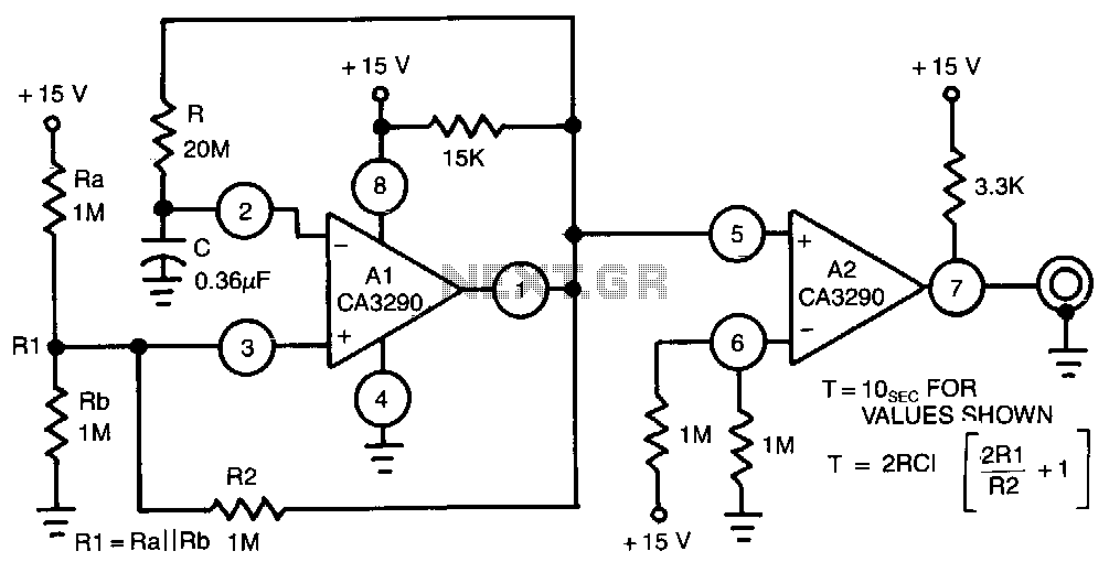
This circuit utilizes one half of the CA3290 BiMOS dual voltage comparator as a conventional multivibrator. The second half ensures frequency stability against the effects of output loading. Large values of the timing resistor, Rl, guarantee long time delays...
The 32-kHz low-power clock oscillator provides several advantages compared to traditional oscillator circuits that utilize a CMOS inverter. These inverter circuits often exhibit issues such as significant fluctuations in supply currents across a 3V to 6V supply range, making...
The small 8-pin PIC12C508 is pre-programmed to generate our 38KHz carrier frequency by simply pulsing I/O-pin GP1. The PIC will generate either 38KHz or 40KHz, depending on the state of GP3 when power is first applied. If you connect...
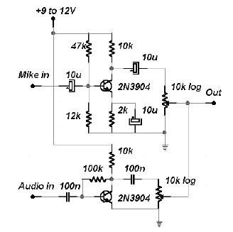
This two-channel audio mixer utilizes 2N3904 transistors to create two preamplifiers. The first preamplifier is designed for high gain, suitable for microphone input, while the second preamplifier allows for control over the audio level input. The audio mixer requires...
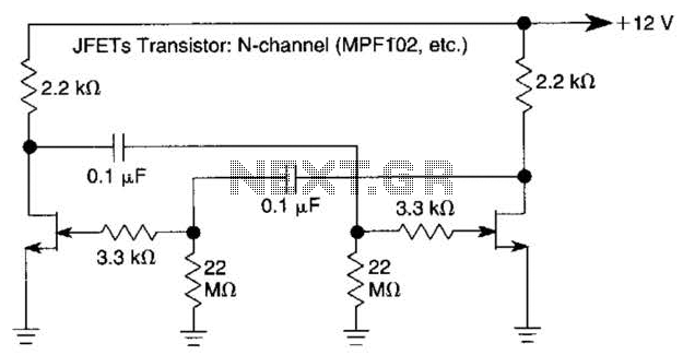
The use of JFETs allows for high resistance and long time constants in this very low frequency multivibrator. The values indicated are for operation at 0.15 Hz. In the context of electronic circuit design, a multivibrator is a circuit that...
Multivibrators are two-state (high or low) output circuits, which include oscillators, timers, and flip-flops. They are primarily used in applications involving timing, pulse generation, or pulse triggering of other devices. There are three types of multivibrators: monostable, bistable, and...