
2000V Low-Current Power Supply

The circuit described operates as a high-voltage generator utilizing a multivibrator configuration. The multivibrator, formed by transistors Q1 and Q2, generates a square wave signal. This square wave oscillation is essential for driving the transformer T1, which steps up the voltage to a significantly higher level. The transformer is designed with a specific impedance ratio, allowing for efficient energy transfer and voltage amplification.
The output from the transformer is an alternating current (AC) signal, which is then fed into a multiplier circuit composed of eight diodes (D1 to D8) arranged in a configuration suitable for voltage multiplication. This arrangement effectively increases the peak voltage output from the transformer, allowing the circuit to achieve the desired high voltage of approximately 2,000 volts.
Capacitors C2 to C9 play a critical role in the multiplier circuit, storing energy and smoothing the output voltage. The requirement for these capacitors to have a voltage rating of 400 volts or higher is essential to ensure reliability and prevent breakdown under high-voltage conditions.
The operational indicator, consisting of NE1 and resistor R2, provides a visual or functional indication of the circuit's performance, ensuring that the system is functioning correctly and safely. Overall, this circuit design is suitable for applications requiring high-voltage generation, leveraging the principles of oscillation and voltage multiplication effectively. In this circuit Ql, Q2, Rl, and CI form a multivibrator. The square wave that results from the oscillation of this circuit (20 to 30 Vpp) is stepped up by T1 (an audio transformer of the type used in radios or small TVs). An 8- to 1,200-Q impedance ratio equates to a turn ratio of 12:1. The ac from the secondary of T1 is applied to the multiplier circuit (D1 to D8 and C2 to C9). NE1/R2 are used as an operating indicator. The circuit will supply about 2,000 V. C2 to C9 should have a 400-V or higher voltage rating.
Related Circuits
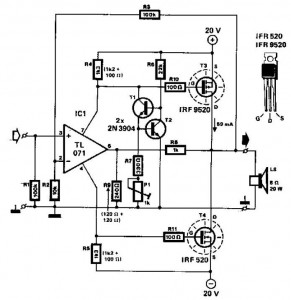
This audio power amplifier employs two complementary MOSFETs (IRF9520 and IRF520) to provide up to 20W output into an 8-ohm speaker. A TL071 operational amplifier functions as the input amplifier. The MOSFETs require heatsinking with a thermal resistance of...
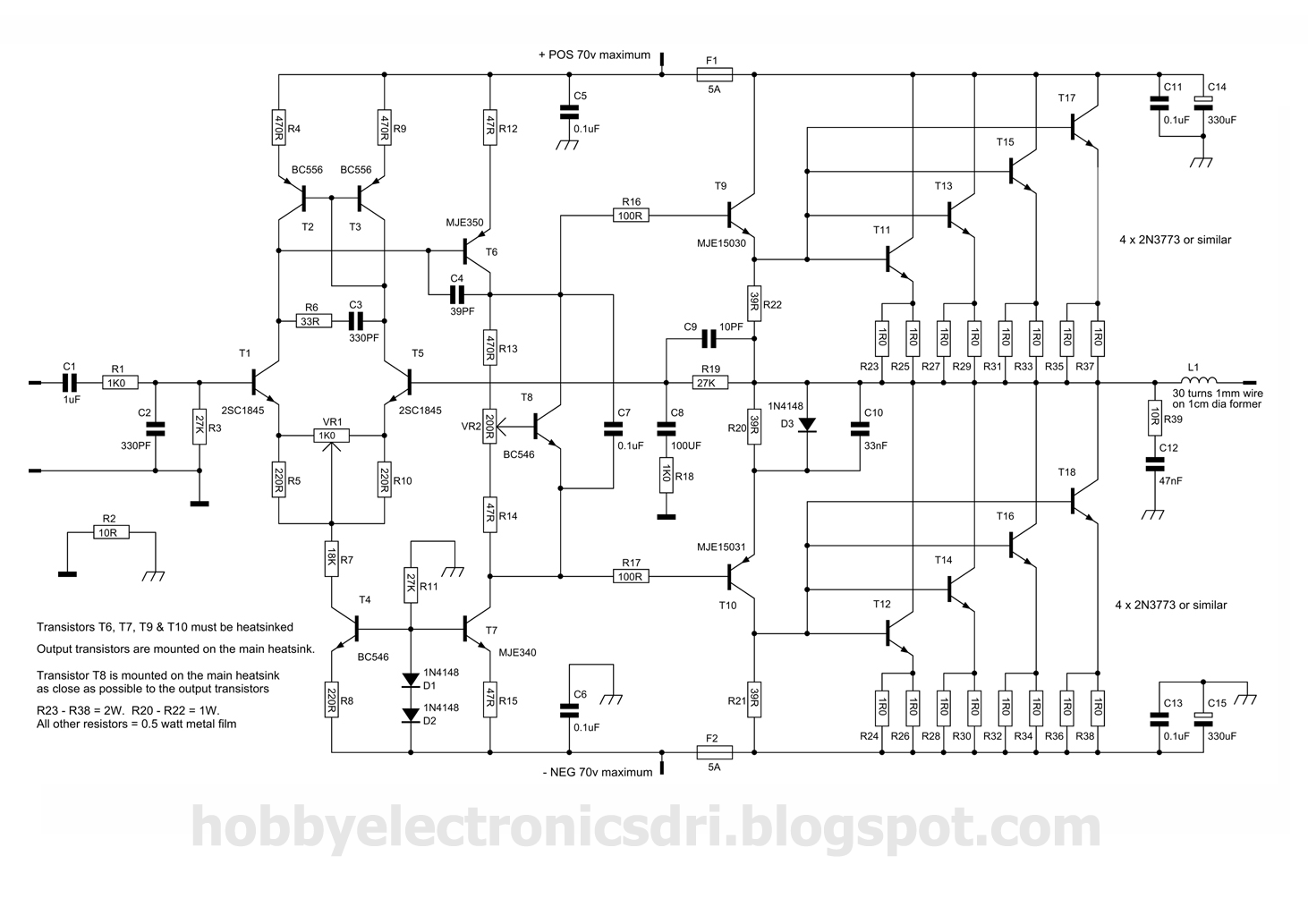
This amplifier was designed to utilize the otherwise unused TO3 power transistors that many hobbyists possess. With proper construction, the module can achieve high-quality performance and is rated for 300 watts into a 4-ohm load, depending on the power...
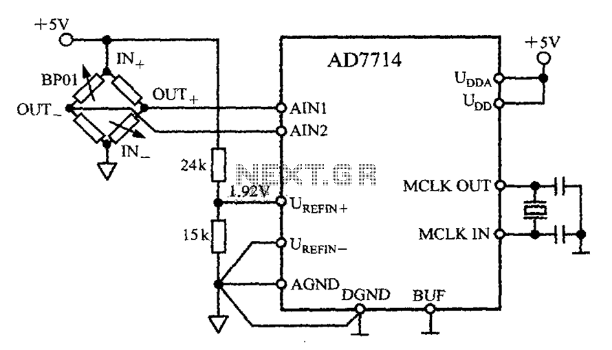
The AD7714 circuit consists of a pressure measurement system featuring the BP01 pressure sensor from Sensym. The BP01 is integrated into a bridge circuit, which produces a differential output voltage. When the sensor is subjected to its rated full-scale...
This simple circuit is designed to provide an output power of approximately 1 watt when connected to a 9-volt power supply. The key advantage of this circuit is its use of a dual Darlington configuration, which increases the input...
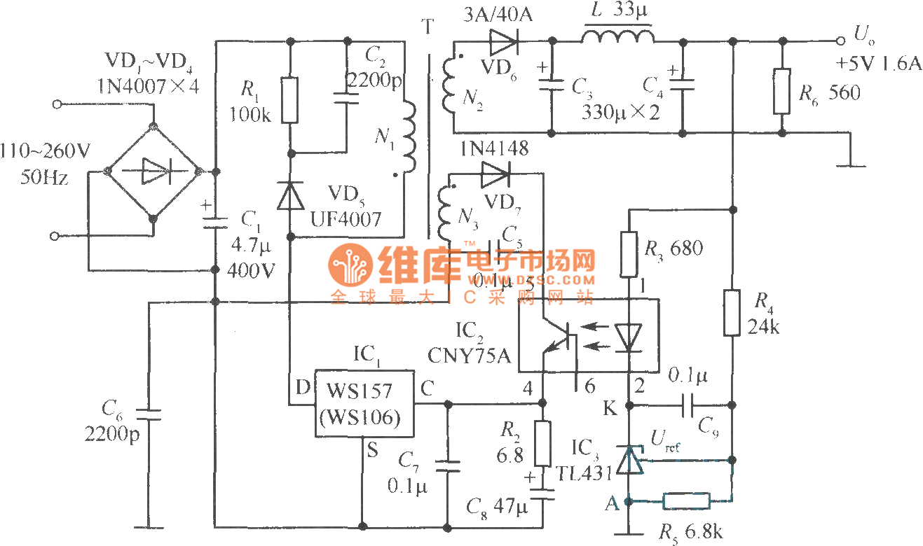
The +5V, 1.6A precision switching power supply circuit is depicted in the figure. This circuit utilizes a photoelectric coupler (CNY75A) and an adjustable precision parallel regulator (TIA31). R3 serves as the current limiting resistor, while R4 and R5 function...
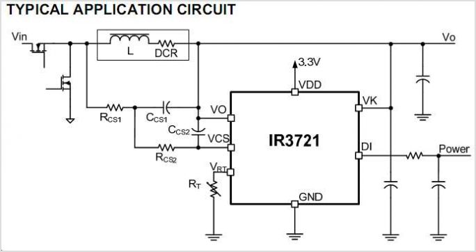
The International Rectifier IRAM109-015SD is a multi-chip hybrid integrated circuit designed specifically for low-power appliance motor control applications, including fans, pumps, and refrigerator compressors. Its compact single in-line package (SIP-S) optimizes PCB space. The device includes several built-in protection...