
+5V 1.6A precision switching power supply circuit

The +5V, 1.6A precision switching power supply circuit is designed to provide a stable voltage output with minimal ripple, making it suitable for sensitive electronic applications. The circuit employs a photoelectric coupler (CNY75A) to isolate the control circuitry from the high-voltage side, enhancing safety and performance. The adjustable precision parallel regulator (TIA31) is used to maintain a constant output voltage, which is critical for ensuring the reliability of the powered devices.
In this circuit, R3 is the current limiting resistor, which protects the components by preventing excessive current flow. R4 and R5 are configured as sampling resistors, enabling the circuit to monitor the output voltage. When the output voltage (Vo) deviates from the desired level, the feedback mechanism compares the voltage across the sampling resistors to a stable reference voltage of 2.5V. This comparison allows for precise adjustments to the output voltage, ensuring it remains at the required +5V level.
The overall design of the circuit emphasizes efficiency and stability, making it suitable for applications that require a reliable power supply. The choice of components, such as the CNY75A for isolation and the TIA31 for regulation, reflects a careful consideration of performance and safety in the design of switching power supplies.The +5V, 1.6A precision switching power supply circuit is as shown in the figure. This circuit increases the photoelectric coupler (CNY75A) and the adjustable precision parallel regulator (TIA31). R3 is the current limiting resistor, R4 and R5 are the sampling resistor. When the Vo changes, the sampling resistor will compare with the 2.5V reference voltage o.. 🔗 External reference
Related Circuits
This is a circuit diagram of a simple circuit in which the LED can be activated only by a gust of air. A condenser microphone (M1) is used to detect breath. When the S1 button is pressed, transistors Q2...
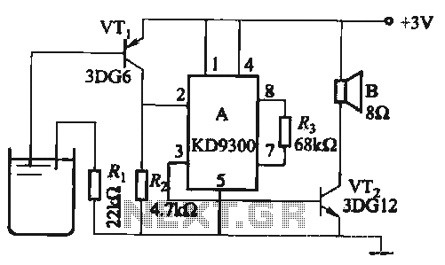
Changing the values of Ri, R2, Cl, and C3 can modify the alarm tone. The circuit utilizes KD9300 music integrated circuits. The circuit described is designed to generate an alarm tone through the manipulation of specific component values within the...
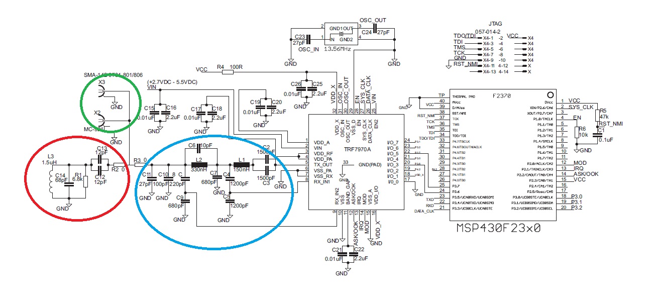
The "green area" is designated for the placement of the TRF7970A's antenna, which should be connected between two 0-ohm resistors. The antenna can be constructed step by step following the guidelines in the document "Antenna Matching for the TRF7960...
This is a non-contact power regulator circuit designed for a light load. By adjusting a 150kΩ potentiometer, phase shift can be achieved, and a trigger voltage is applied to the gate of a bidirectional thyristor through a bidirectional trigger...
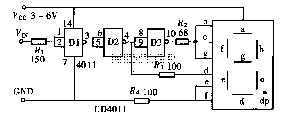
The door circuit logic pen text display can take many forms, utilizing various logic gates such as inverters, NAND gates, NOR gates, and others. A logical pen, exemplified by the NAND gate CD4011, can be used in conjunction with...
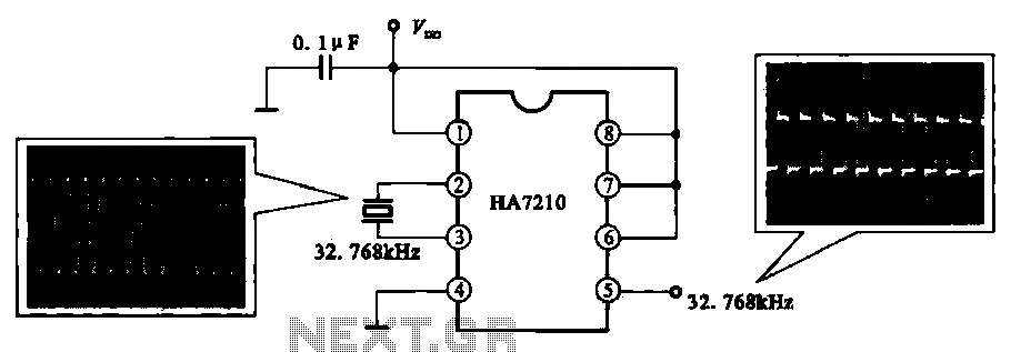
This circuit illustrates a 32.768 kHz micro-power clock oscillator, suitable for use in mobile phones, laptop computers, and home appliances. It generates a clock signal that can be utilized in various applications. The 32.768 kHz micro-power clock oscillator circuit is...