
200Mhz cascode amplifier

The 200 MHz JFET cascode circuit is designed to achieve high-frequency performance while minimizing undesirable effects such as cross-modulation. The cascode configuration, which consists of two JFETs arranged in series, allows for improved gain stability and bandwidth. The upper JFET is responsible for providing a high impedance to the input signal, while the lower JFET amplifies the signal with a lower output impedance.
In this circuit, the automatic gain control (AGC) is implemented by adjusting the biasing of the upper cascode JFET. This allows for dynamic control of the gain based on the input signal level, ensuring that the output remains within a specified range despite variations in the input. The absence of neutralization simplifies the design and enhances reliability, making it suitable for applications where consistent performance is critical.
The requirement that the Idss of the upper JFET exceeds that of the lower JFET is vital for maintaining the desired operating point and ensuring that the upper device can effectively handle the larger signal levels without distortion. This design consideration is critical for achieving optimal performance in high-frequency applications, where signal integrity is paramount.
Overall, this JFET cascode circuit is an effective solution for high-frequency amplification needs, balancing performance with simplicity and reliability.This 200 MHz JFET cascode circuit features low cross-modulation, large signal handling ability, no neutralization, and AGC controlled by biasing the upper cascode JFET The only special requirement of this circuit is that Idss of the upper unit must be greater than that of the lower unit.
Related Circuits
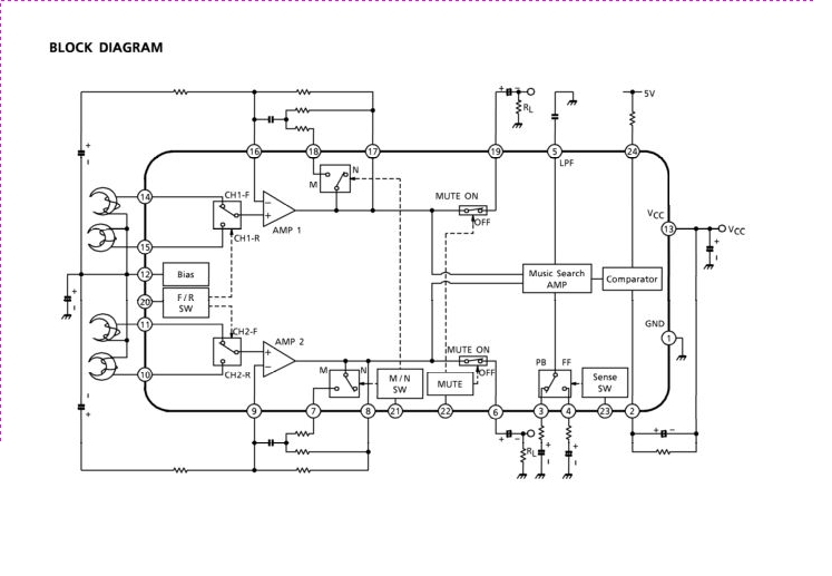
The TA2042F is a dual preamplifier with a music interval detection circuit designed for auto-reverse car stereo systems. This integrated circuit (IC) features dual amplifiers, a forward/reverse control switch, and a metal/normal tape equalizer. The TA2042F serves as a pivotal...

This design utilizes a well-established circuit topology for the power amplifier, employing a single-rail supply of approximately 60V and capacitor coupling for the speaker(s). The benefits for a guitar amplifier include simple circuitry, even with relatively high power outputs,...

This is a circuit for an accelerometer amplifier. It is a straightforward circuit. A precision accelerometer requires an inverting mode amplifier since these devices typically output charge. This amplifier converts charges into a voltage output. The circuit presented below...
A homebrew 2M transceiver was designed for mobile use, eliminating the need for a fist microphone. A low-cost personal hands-free kit for mobile phones was initially considered, but it resulted in inadequate audio performance. The circuit utilized had a...
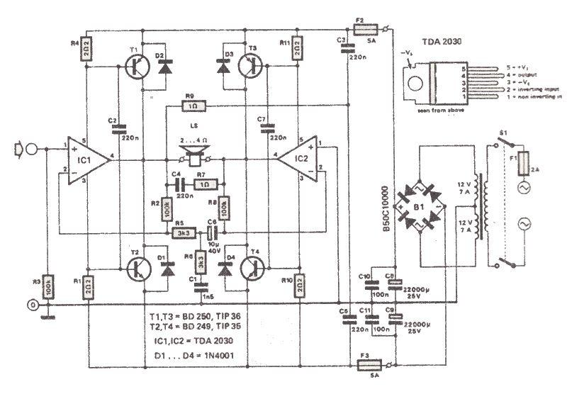
The TDA2030 is a low-cost audio power amplifier capable of delivering high output audio power up to 200 watts with a load impedance of 2 to 4 ohms. This high-power audio amplifier is built around the TDA2030 audio amplifier...
The circuit was designed to increase an input signal of 4 Watts to 6 Watts, operating within the VHF radio frequency band, specifically for FM transmission. This circuit is engineered to amplify radio frequency signals in the VHF band, which...