
20dB antenna amplifier circuit diagram electronic project

The circuit design involves utilizing a BF200 transistor as the primary amplification element, which is known for its high-frequency performance and low noise characteristics. The BF214 transistors serve as additional amplification stages, enhancing the overall gain of the circuit.
To ensure optimal performance, the placement of the antenna amplifier is crucial; it should be installed as close to the antenna as possible to minimize signal loss and maintain signal integrity. The use of a power supply that delivers a voltage range of 6 to 12 volts DC allows for flexibility in powering the circuit, accommodating various power supply options available in the field.
For the connection of the power supply to the amplifier circuit, employing a shielded cable or coaxial cable is vital. This choice helps to reduce electromagnetic interference (EMI) and ensures that the signal remains clean as it travels from the power source to the amplifier. Additionally, the shielded cable provides protection against external noise, which is especially important in RF applications.
The overall design should consider the thermal management of the transistors, ensuring that adequate heat dissipation is provided, especially under high load conditions. Proper grounding techniques should also be implemented to prevent ground loops and enhance circuit stability.
In summary, the circuit requires careful attention to component selection, placement, and interconnection methods to achieve the desired performance in antenna amplification applications.T1 transistor must be BF200 type (or similar ) and the other transistors can be BF214 type. For high efficiency, the antenna amplifier must be placed at a small distance from antenna. This amplifier circuit can be powered using a power supply that supply an output voltage between 6 and 12 volts DC. For powering this device you need to use a sh ielded cable or a coaxial cable. 🔗 External reference
Related Circuits
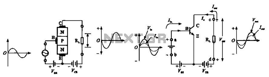
The common emitter amplifier circuit exhibits a specific phase relationship between its input and output signals. This configuration is widely utilized in various electronic devices primarily for its high voltage gain. However, the output impedance is higher than the...
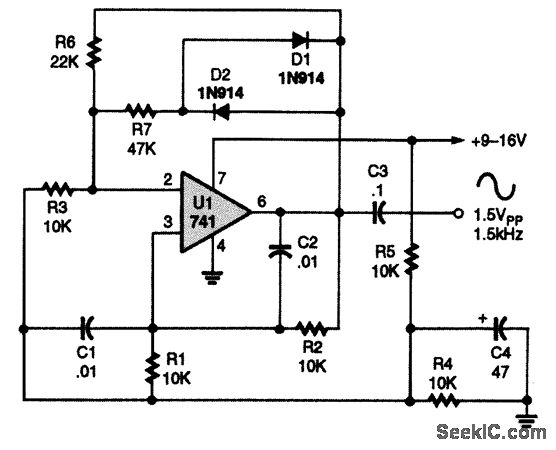
A 741 operational amplifier is configured within a Wien-bridge audio sine-wave oscillator circuit. The components C1, C2, R1, and R2 are responsible for determining the operating frequency of the circuit. By utilizing NPO capacitors and metal-film resistors, the oscillator...
This circuit measures the distance covered during a walk. The hardware is located in a small box that can be slipped into a pants pocket. The display is designed such that the leftmost display, D2 (the most significant digit),...

This circuit operates with 230V and can be used to decorate parties. It features a DIAC ER 900 and a TRIAC BTW 11-400. The circuit utilizes a DIAC (Diode for Alternating Current) and a TRIAC (Triode for Alternating Current) to...
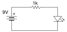
Beginner's Tutorial 1: Building a Circuit on Breadboard - how to build a simple and easy circuit on a breadboard for beginners in electronics. Learn to use an LED and a resistor. This tutorial serves as an introductory guide for...
This is a battery charger circuit that has the advantage of automatically disconnecting the battery when charging is complete. The voltage sensor used in this circuit is the LM301 IC, which serves to disconnect the battery when the charging...