
Automatic battery charger circuit using lm301-2

The battery charger circuit is designed to efficiently manage the charging of batteries while ensuring safety and longevity. The circuit employs the LM301 integrated circuit as a voltage sensor, which plays a critical role in monitoring the battery voltage during the charging process. When the voltage reaches the predefined threshold, the LM301 activates a cutoff mechanism that disconnects the battery from the charger, preventing overcharging and potential damage.
The LM350, acting as a variable voltage regulator, allows for the adjustment of the output voltage within the specified range of 12.6 to 14.4 volts. This flexibility is essential for accommodating different battery types and ensuring optimal charging conditions. The output voltage can be fine-tuned by adjusting external resistors connected to the LM350, which acts as a voltage divider. This feature is particularly useful for maintaining the health of lead-acid batteries, which are sensitive to overvoltage.
To enhance the reliability of the circuit, a thermal management system is recommended. As the charging process generates heat, the inclusion of a heat sink or an active cooling fan can help dissipate excess heat, thereby maintaining the performance of the components and prolonging their lifespan. The automatic fan controller can be designed to activate based on temperature thresholds, ensuring that cooling is only applied when necessary, thus optimizing energy usage.
The power supply for this circuit is specified as an 18-volt source, which provides sufficient headroom for the LM350 to regulate the output voltage effectively while allowing for voltage drops across other components in the circuit. The design includes a schematic diagram that visually represents the connections and components involved, facilitating easier understanding and implementation of the circuit. Additionally, a printed circuit board (PCB) layout is provided, allowing for efficient assembly and minimizing errors during construction. This PCB is designed to accommodate the LM301 and LM350, ensuring proper placement and connections for optimal performance.This is a battery charger circuit, this circuit has advantages, which can cut off electrical charging of the battery automatically. Voltage sensor used in this circuit is the LM301 IC2. This sensor serves to disconnect the battery if the charging voltage has reached the limit. LM350 is a variable volt regulator IC that functions as a voltage divid er output. Limit the voltage used to perform the charging battery is 12. 6 to 14. 4 volts. Batteries can be damaged if the charging voltage exceeds the voltage limit, or the battery is filled in too long. Here is a schematic drawing automatic battery charger: During the charging process, this circuit will increase the temperature.
advised to put a good cooler or can combine with Automatic fan controller uses the temperature. Voltage source used is a 18 Volt power supply. Here I also include a PCB (printed circuit board) of the automatic battery charger circuit using LM301 and you can also download it. 🔗 External reference
Related Circuits
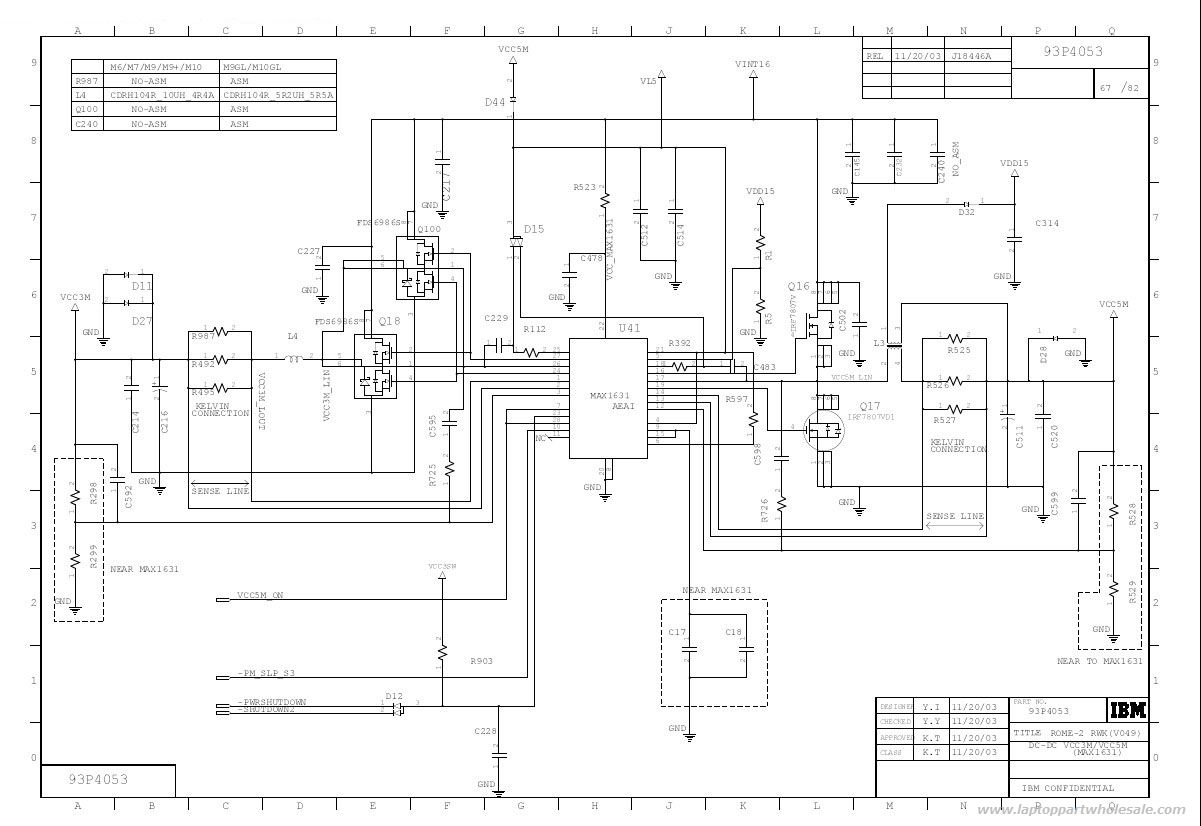
This is an IBM ThinkPad T40 power control circuit. This circuit is based on the MAX1631 IC, which is a multi-output, low-noise power supply. The IBM ThinkPad T40 power control circuit utilizes the MAX1631 integrated circuit (IC) to provide stable...
A battery-operated Tesla coil is being developed, and assistance is needed for converting direct current (DC) to alternating current (AC) to power a high-voltage transformer. To convert DC to AC for powering a high-voltage transformer in a Tesla coil circuit,...
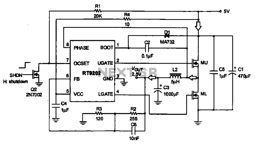
A 5V to 2.5V voltage regulator circuit is designed for use in computer motherboards. At its core, this circuit utilizes the RT9202 power management chip. The RT9202 functions as a switching pulse generating circuit, which, upon startup, converts a...
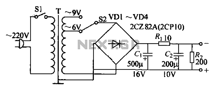
The adjustable current power supply circuit operates at 6V and 9V, utilizing a minimal number of components, which facilitates easy assembly. The circuit can deliver an adjustable output current of up to 100mA, serving as a suitable alternative to...

The following diagram is the clock generator circuit diagram built using NAND gate logic integrated circuits (ICs). The circuit can utilize either the IC 7400, which is a TTL type, or the IC 4011, which is a CMOS type....

The sound produced imitates the rise and fall of an American police siren. When first switched on, the 10 µF capacitor is discharged, and both transistors are off. When the push button switch is pressed, the 10 µF capacitor...