
20dB VHF AmplifierCircuit Using BF197 Transistor

The 20 dB VHF amplifier circuit is designed to amplify very high frequency signals, making it suitable for applications such as radio frequency (RF) communications, television receivers, and other VHF applications. The circuit employs a BF197 transistor, which is a high-frequency N-channel JFET known for its low noise and high gain characteristics.
The circuit typically consists of a few key components: the BF197 transistor, resistors for biasing and load, capacitors for coupling and bypassing, and possibly an inductor for tuning. The input signal is fed into the gate of the BF197 through a coupling capacitor, which blocks any DC component from the signal source. The gate resistor is used to set the bias point of the transistor, ensuring it operates in the active region for optimal amplification.
The output is taken from the drain of the transistor, which is connected to a load resistor. The load resistor determines the gain and output impedance of the amplifier. A bypass capacitor is often placed across the source resistor to enhance the gain at the operating frequency by providing an AC ground at the source terminal.
To maintain stability and prevent oscillations, feedback may be incorporated into the design. This can be achieved by connecting a portion of the output back to the input through a feedback resistor. The amplifier can be tuned for specific frequency responses by adjusting the values of the capacitors and resistors, allowing it to operate effectively within the VHF range.
Overall, this circuit provides a straightforward and efficient solution for amplifying VHF signals, making it a valuable component in various electronic systems requiring signal enhancement.The following circuit shows about 20dB VHF Amplifier Circuit Diagram. This circuit using the BF197 Transistor. Features: simple circuit, with .. 🔗 External reference
Related Circuits
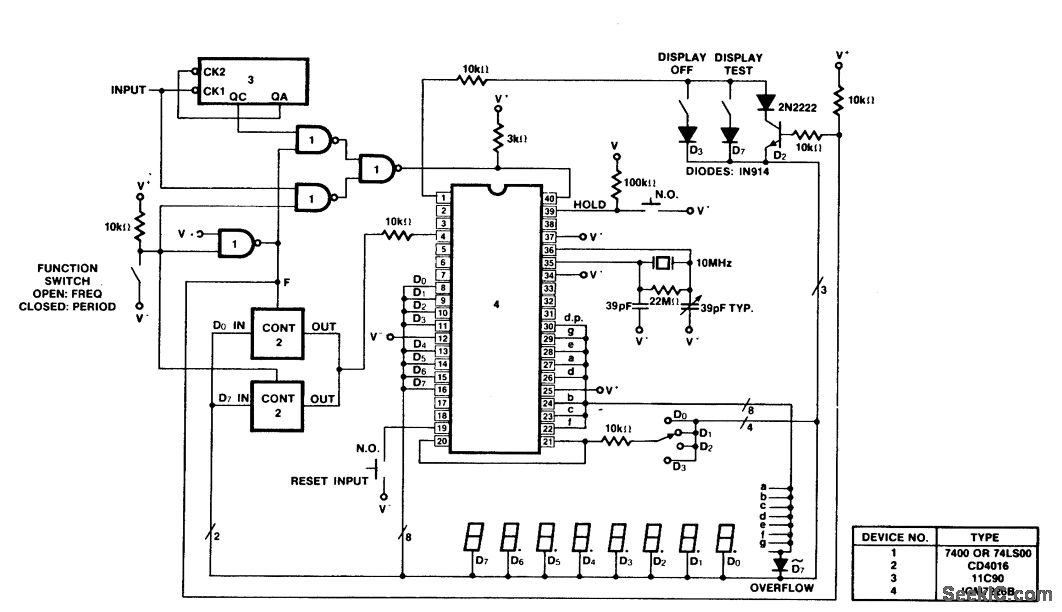
A 100 MHz frequency and period counter is constructed using the Intersil ICM7226B in a 40-pin DIP package. This circuit incorporates a CD4016 analog multiplexer to route the digital outputs back to the function input. The CD4016 operates as...
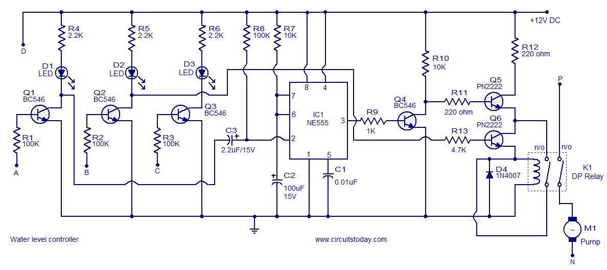
A simple water level controller circuit utilizing a 555 integrated circuit (IC) and six transistors. A relay is employed for controlling the pump motor. This water level controller circuit is designed to monitor and manage the water level in a...
Construct a basic audio amplifier utilizing transistors. While integrated circuit (IC) designs are available for this purpose, the intention is to use transistors to gain practical knowledge about their amplification capabilities. The article "Amplifier Basics - How Amps Work...
A 12V power supply is an essential and useful resource for laboratories, as it is employed by a wide range of electronic circuits and devices. A 12V power supply circuit can be constructed based on specific ampere requirements. A...
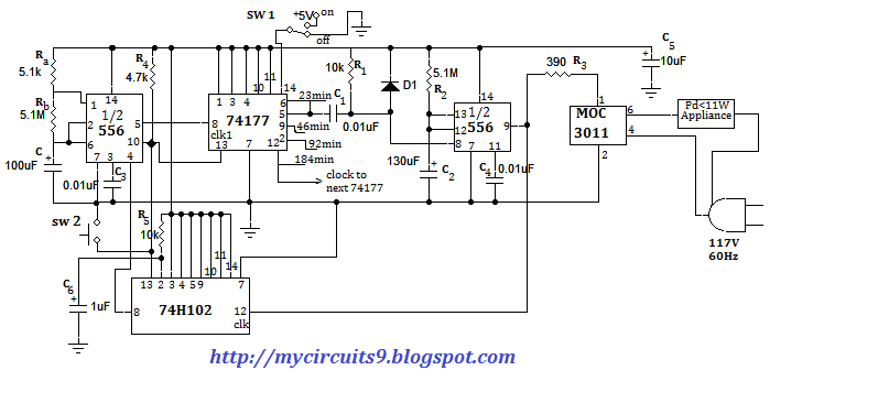
This document presents an electronic project focused on device control using a timer. This circuit allows for the activation of an appliance at a specified time for a predetermined duration. It can be applied to manage the operation of...
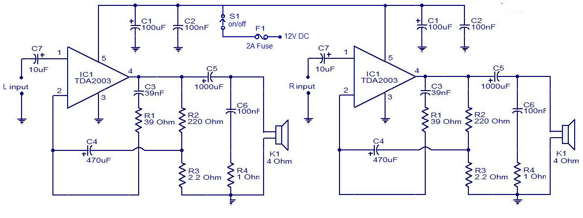
The circuit is easy to construct. The TDA2003 is an integrated radio amplifier from ST Microelectronics that features short circuit protection for all pins, thermal protection, low harmonic distortion, and low crossover distortion. In the circuit provided, the TDA2003...