
Water level controller circuit using transistors and NE555 timer IC

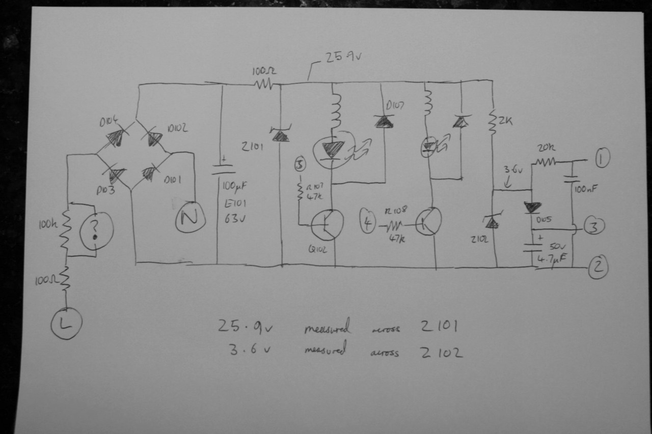
This water level controller circuit is designed to monitor and manage the water level in a tank or reservoir using a 555 timer IC, which serves as the central control unit. The circuit operates based on the principles of detecting water levels through conductive probes or float switches, which trigger the operation of a relay to control a pump motor.
The 555 timer can be configured in astable or monostable mode, but for this application, it is typically set up in monostable mode to provide a pulse when the water level drops below a certain threshold. The six transistors in the circuit are used to amplify the control signals and drive the relay, allowing for the switching of higher currents needed for the pump motor.
When the water level falls below the designated point, the probes detect this condition, and the 555 timer outputs a signal. This signal is fed to the first transistor, which acts as a switch to turn on the subsequent transistors in the circuit. Each transistor amplifies the current until the final transistor activates the relay. The relay, in turn, energizes the pump motor, which begins to fill the tank with water.
Conversely, when the water level rises to the set point, the probes again detect this condition, causing the 555 timer to cease its output signal. This action turns off the transistors sequentially, deactivating the relay and stopping the pump motor from operating, thus preventing overflow.
The circuit design may include additional features such as LED indicators to show the operational status of the pump, as well as protection diodes to prevent back EMF from damaging the transistors when the relay coil is de-energized. Overall, this water level controller circuit is a practical and efficient solution for automating water management in various applications.A very simple water level controller circuit based on 555 IC and 6 transistors. A relay is used for switching the pump motor.. 🔗 External reference
Related Circuits
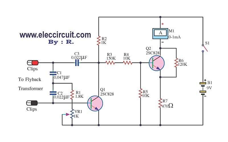
The circuit tests a flyback transformer used in televisions, and it is simple, easy, and inexpensive to construct. A friend who is a TV repairman provided this information. The circuit designed for testing a flyback transformer is essential for diagnosing...
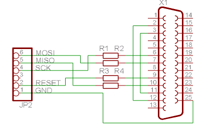
The Atmega 128 is similar to other AVR microcontrollers. It is in-system programmable (ISP). An earlier article discussed the AVR ISP programmer, which utilizes a 74HC244 buffer for safety when programming the AVR. However, if a programmer for the...
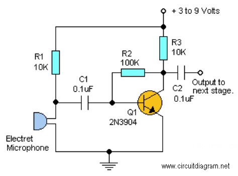
This project requires expensive hardware, including a microphone and amplifier, along with sophisticated audio analysis on the microcontroller. Even a complete microphone with an amplifier circuit does not yield the desired results, as noted in the product comments. The...
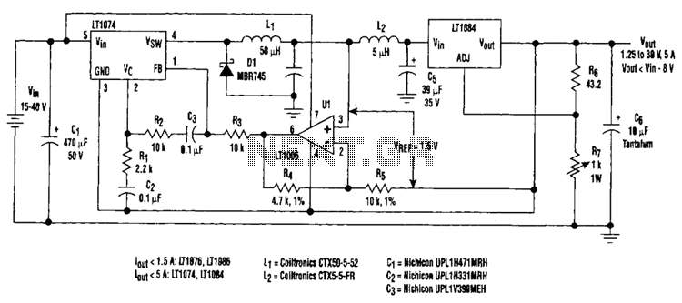
Large input-to-output voltage differentials, caused by wide input voltage variations, reduce a linear regulator's efficiency and increase its power dissipation. A switching preregulator can reduce this power dissipation by minimizing the voltage drop across an adjustable linear regulator to...
Have you ever imagined controlling your home appliances using your cell phone? Numerous circuits exist for this application, typically utilizing a telephone. This circuit has been modified and redesigned for compatibility with a standard cell phone headphone jack. To...
This may appear to be a highly detailed post; however, it is being written to assist others who are experiencing a similar frustrating search for 12V timers that possess functionalities comparable to those found in mains timers. The intention...