
220V LED Flasher

The 220V LED flasher circuit operates by utilizing a simple arrangement of components to create a flashing effect suitable for decorative lighting applications, such as Christmas tree lamps. The primary components include a resistor (R1), which is essential for controlling the current flow through the LED, ensuring it operates within safe limits. The circuit may also include additional components such as a capacitor for timing, a diode for rectification, and a transistor to switch the LED on and off.
In a typical configuration, the resistor R1 is connected in series with the LED, which is powered by a 220V AC supply. The capacitor, when included, is connected in parallel with the LED, forming an RC timing circuit that determines the flashing rate. The diode is used to convert the AC voltage to DC, allowing the LED to flash appropriately. The transistor acts as a switch, controlled by the charging and discharging of the capacitor, enabling the LED to turn on and off at a specified frequency.
This circuit can be assembled on a breadboard or a printed circuit board (PCB) for more permanent installations. The simplicity of the design, combined with readily available components, makes this LED flasher circuit an ideal choice for festive lighting applications, providing an energy-efficient and visually appealing solution. Proper safety precautions should be taken when working with high-voltage circuits, including the use of insulated tools and components rated for the operating voltage.This is a 220V LED flasher circuit which is intended as a reliable replacement to thermally-activated switches used for Christmas tree lamp-flashing. This a cheap circuit and easy to build. Schematic diagram: Component Parts: R1_________ 10.. 🔗 External reference
Related Circuits
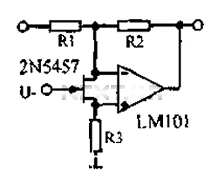
A 1.53 voltage-controlled gain amplifier (VGA) utilizes a FET connected between the two inputs of the operational amplifier (op-amp) as a voltage-controlled resistance. The resistance changes linearly with voltage and varies from several dozen square ohms, exhibiting excellent control...
If we have a lot of parallel telephones on a telephone line, we needed a unit that will have the possibility of showing if somebody of the telephone has raised the earphone. Our this possibility give the circuit. The...

This is a versatile Low-Frequency Oscillator (LFO) designed for various modulation applications. The frequency of the LFO can be controlled by voltage, enhancing the range of sound possibilities. The pulse width of the rectangular wave can be adjusted between...

This circuit is designed to convert 12V DC from lead-acid batteries to 250V AC, suitable for use in cars, boats, or mobile homes. It provides sufficient power for small electronics such as lamps or soldering irons. The circuit comprises...

One reason commercial soldering stations are expensive is that they generally require soldering irons with built-in temperature sensors, such as thermocouples. This circuit eliminates the need for a special sensor by sensing the temperature of a soldering iron heating...
The circuit utilizes standard components, produces a good sine wave, and exhibits a degree of immunity to the specific operational amplifier it is designed around. However, it can be easily misunderstood, and oversimplifications regarding its operation may lead designers...