
Voltage controlled gain amplifier circuit diagram

The voltage-controlled gain amplifier operates by modulating the resistance of the FET based on an input voltage signal. This configuration allows for precise control of the gain of the amplifier, making it suitable for applications requiring variable amplification levels. The FET, acting as a voltage-controlled resistor, provides a linear relationship between the control voltage and the resistance, ensuring predictable performance across a range of input conditions.
The circuit typically comprises an op-amp configured in a non-inverting or inverting configuration, depending on the desired gain characteristics. The FET's source and drain terminals are connected to the op-amp inputs, while the gate terminal receives the control voltage. As the control voltage varies, the resistance of the FET alters, thereby changing the gain of the op-amp circuit in a linear fashion.
The performance of the VGA can be further enhanced by selecting appropriate op-amps and FETs that exhibit low distortion and high linearity. Additionally, feedback networks can be incorporated to stabilize the gain and improve bandwidth. Such configurations are widely used in audio processing, instrumentation, and communication systems, where adjustable gain is essential for signal integrity and processing efficiency.
Overall, the design and implementation of a voltage-controlled gain amplifier using a FET as a variable resistor provide an effective means of achieving dynamic control over amplification, making it a valuable component in various electronic applications.1.53 voltage controlled gain amplifier FET connected between the two inputs to the op amp as voltage-controlled resistance, resistance changes linearly with voltage, varies fro m several dozen square, with excellent control characteristics. Each of the resistance depends on the op amp.
Related Circuits
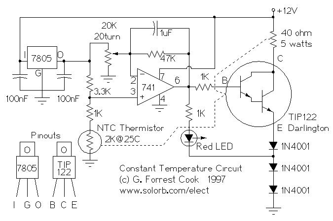
Constant Temperature Circuit. G. Forrest Cook 1997. Introduction: This circuit is a generic low-power temperature controller that can be used for stabilizing temperature. The constant temperature circuit described is designed to maintain a stable temperature in various applications, utilizing low...
Switching regulator subsystems intended for use as DC to DC converters. 3V to 40 Volt DC Converter circuit. The use of switching regulators is becoming more pronounced than that of linear regulators because the size reductions in new equipment...
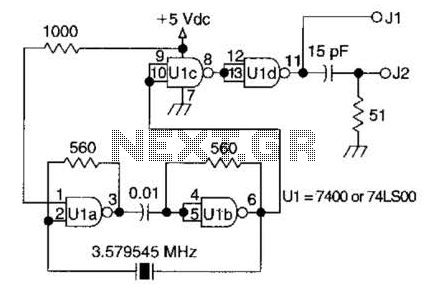
A circuit utilizing one 7400 TTL can operate with fundamental type crystals ranging from 1 to approximately 13 MHz. The output is rich in harmonics, making this oscillator suitable for calibration and testing applications. The circuit in question employs a...
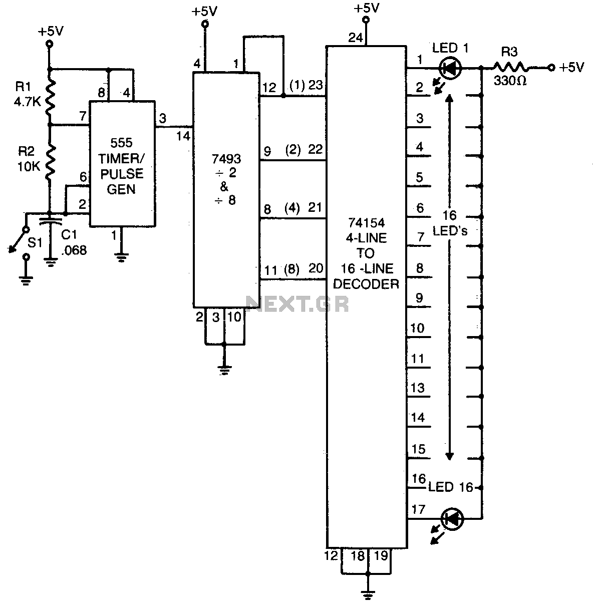
The 555 timer generates a rapid series of pulses when switch SI is in the open position. These pulses are grouped into sets of 16 and converted into binary format by the 7493 counter. The binary output is then...
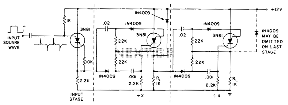
The circuit operation is initiated by a positive edge signal. The anodes of the triac switches are activated while the cathodes of the switches remain closed. A male-female IN4009 diode is utilized for positive transient suppression, ensuring that the...
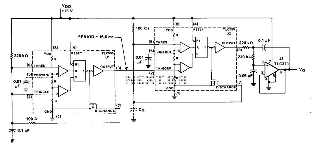
The timer U1 operates as a free-running oscillator at 60 Hz, providing trigger pulses to timer U2, which functions in monostable mode. Resistor R1 is fixed, while capacitor Cx is the capacitor being measured. The output of U2 is...