
230V Blinking LED

This circuit operates by utilizing the properties of the diac, which acts as a switching device. Initially, when power is applied to the circuit, the capacitor begins to charge through the current-limiting resistor and the rectifying diode (1N4007). The charging process continues until the voltage across the capacitor reaches the breakdown voltage of the diac, which is typically around 30V. At this point, the diac enters its conductive state, allowing the stored charge in the capacitor to rapidly discharge through the diac and the LED, creating a visible blinking effect.
The frequency of the blinking LED is influenced by the RC time constant of the circuit, which is determined by the product of the resistance (R) and capacitance (C) values. The two resistors can be configured to fine-tune the charging time of the capacitor, thereby adjusting the blinking rate of the LED. Additionally, the use of two capacitors can introduce further flexibility in timing adjustments, potentially allowing for different blinking patterns or durations.
It is important to select components that can handle the operating voltage and current levels. The diode (1N4007) is rated for 1A and can withstand reverse voltages up to 1000V, making it suitable for this application. The diac should also be chosen based on its breakdown voltage and current handling capabilities to ensure reliable operation. The capacitors must be rated for voltages higher than 40V to prevent breakdown during operation.
Overall, this circuit serves as an effective and simple solution for generating a pulsating light signal, suitable for various signaling applications in electronic projects. Proper selection of component values and ratings is essential for optimal performance and reliability of the circuit.A pulsating light for a certain signaling. Voltage was 230V. So I decided to make a simple circuit, consisted of a LED diode, two capacitors, two resistors, a diac and a diode. Activity of the circuit is extraordinarily simple. The capacitor charges by the diode and the resistor. When the voltage on the capacitor achieves 30V the diac "releases" the electrical tension and the capacitor empties thorough the diac, LED blinks.
Time base is dependent from the capacitor and the resistor, which is in series with diode 1N4007. Capacitor must be at least for 40V. 🔗 External reference
Related Circuits
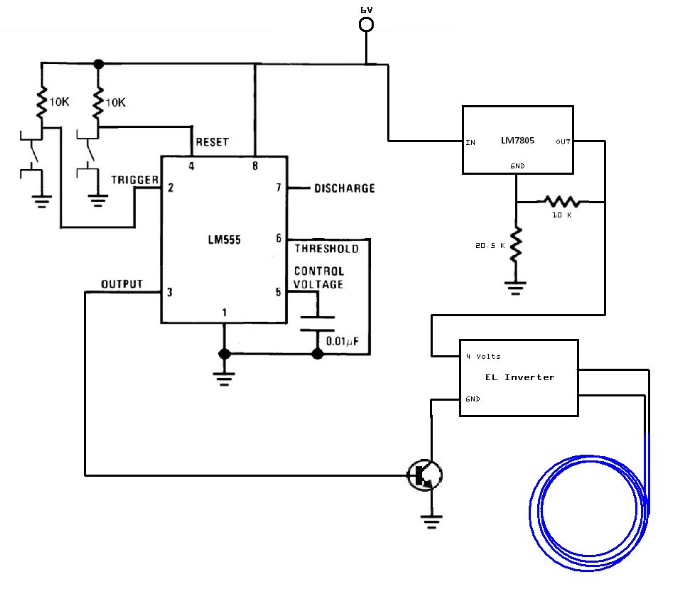
The circuit utilized for this project is quite simple. Some may criticize the omission of decoupling capacitors for the LM7805 voltage regulator. The circuit in question employs the LM7805 voltage regulator, which is designed to provide a stable output voltage...
The light is blinking instead of dimming. A specific software was used to illuminate the bulb without dimming, which includes the following code: ```cpp unsigned int i = 1; void setup() { Serial.begin(9600); ...
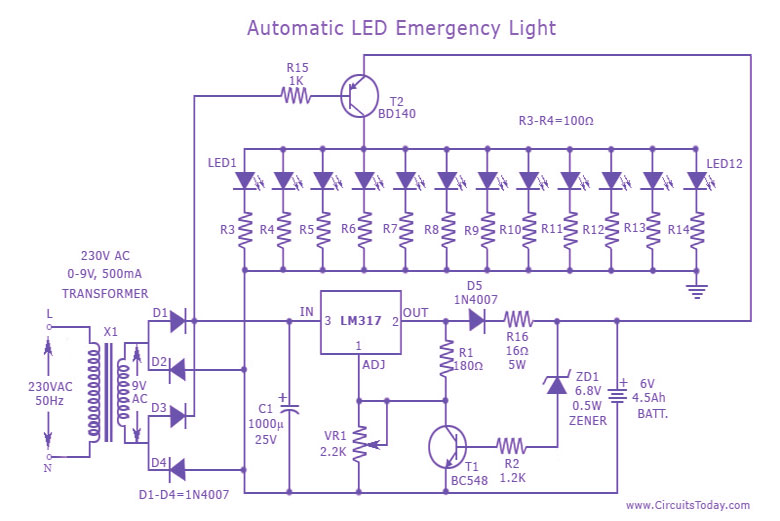
This is a cost-effective and straightforward emergency light circuit developed for CircuitsToday. It is an automatic emergency lamp with daylight sensing capabilities, meaning it detects darkness and turns on automatically, while also sensing daylight to turn off. The circuit...
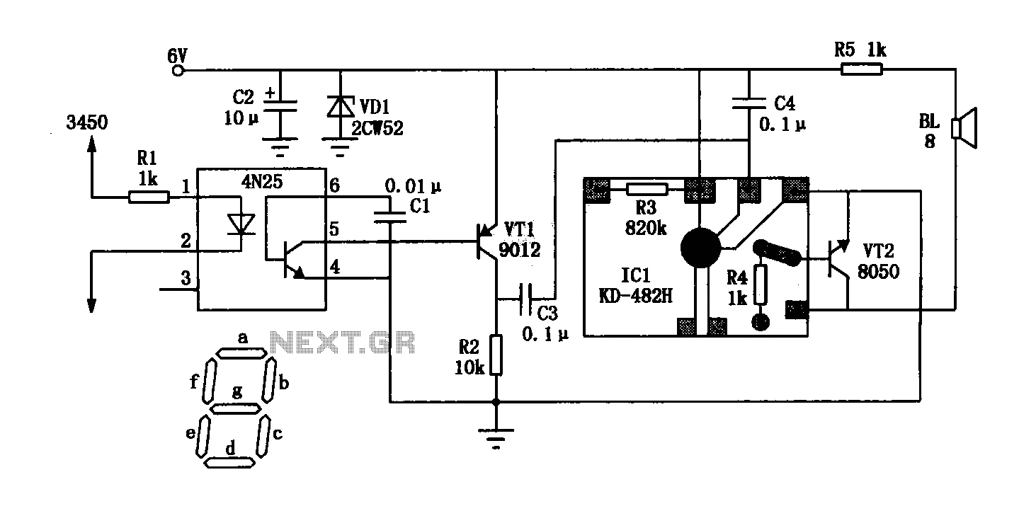
The General Dynamic LED digital clock lacks a timekeeping function, but by adding a simple circuit, it can incorporate this feature. The integrated circuit (IC) includes a programmable mute function, which is inactive from 23:00 to 5:00 to avoid...

In Part 2 of the Arduino masterclass, a weather station is built to measure temperature in degrees Celsius and relative humidity as a percentage. New components and theory are introduced, and practical application is emphasized. While LEDs are effective...

Some time ago, a Pong game was developed as an initial microcontroller project using a 5G-7 LED display, but it was not pursued further. Recently, a hard hat was provided as part of a uniform for an engineering competition,...