
Hidden Tron shirt controlled with a SR Latch

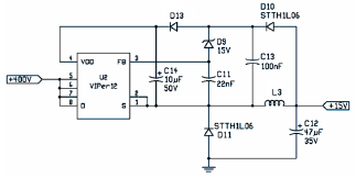
The circuit in question employs the LM7805 voltage regulator, which is designed to provide a stable output voltage of 5V from a higher input voltage. The LM7805 is a linear voltage regulator that requires a minimum input voltage, typically around 7V to 35V, to function correctly.
In a typical configuration, the input voltage is applied to the input pin of the LM7805, while the output pin delivers the regulated 5V. The ground pin of the regulator connects to the circuit's common ground. It is essential to include adequate input and output capacitors to ensure stability and transient response. A common practice is to use a 0.33μF ceramic capacitor at the input and a 0.1μF ceramic capacitor at the output. These capacitors help filter out high-frequency noise and provide a stable voltage under varying load conditions.
While the original description notes the absence of decoupling capacitors, it is important to highlight that these components can significantly enhance the performance of the regulator by preventing oscillations and improving transient response. In applications where the load may change rapidly, such as digital circuits, including decoupling capacitors close to the load is advisable.
The overall circuit should be designed with careful attention to the layout, ensuring that the input and output connections are as short as possible to minimize inductance and potential noise. Additionally, thermal management should be considered, as the LM7805 may dissipate heat depending on the input voltage and load current. A heatsink may be necessary if the power dissipation exceeds the regulator's thermal limits.
In summary, the circuit leverages the LM7805 voltage regulator to achieve a stable 5V output, and while the basic design is straightforward, the inclusion of decoupling capacitors and attention to layout and thermal management are crucial for optimal performance.The circuit used for this project is really straight forward. Many would likely criticize me that I didn`t use decoupling capacitors for the LM7805 vo.. 🔗 External reference
Related Circuits
This circuit operates at 73 MHz and is designed for controlling halogen lights through radio frequency remote control. The primary function is to toggle the power state of a halogen lamp. When the button on the remote control is...
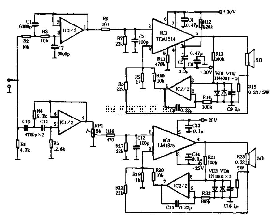
The mechanical and electrical schematic in Figure 5 illustrates a simple circuit comprising several components. The first component is an electronic crossover section utilizing the NE5532 operational amplifier, which is known as the "Emperor of the op-amp." This section...

A simple linear voltage-controlled amplifier can be constructed with one operational amplifier (op amp) and two junction field-effect transistors (JFETs). This amplifier can achieve an 80-dB dynamic control range with less than ±0.2% linearity error for 0 V. The described...
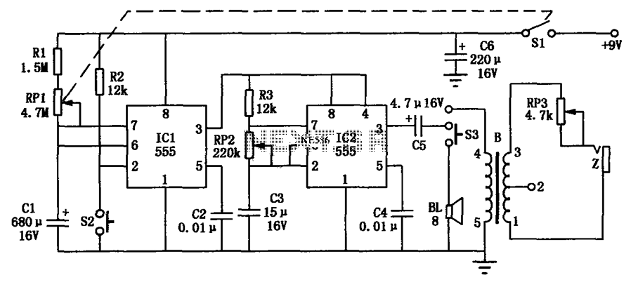
The hypnosis massage device is a compact electronic timing circuit that utilizes two 555 timers to address the health needs of individuals seeking relaxation. The circuit comprises three main components: a timer circuit, a hypnosis circuit, and a massage...
The following file is an application note describing the two stages of an electronic ballast for a 250 W HID metal halide lamp. The components include. The application note outlines a two-stage electronic ballast designed specifically for a 250 W...
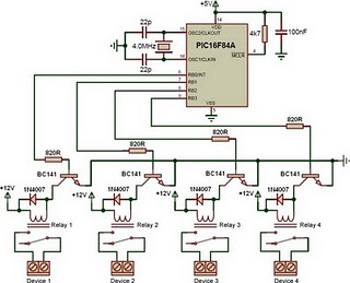
This is a relay driver based on a PIC16F84A microcontroller. The board includes four relays, allowing control of four distinct outputs. The relay driver circuit utilizing the PIC16F84A microcontroller is designed for controlling multiple devices or systems through relay activation....