
24 Second Countdown Timer Circuit

The 24-second countdown timer circuit operates using a combination of logic gates and flip-flops integrated into the 74LS series of Schottky ICs, which are known for their fast switching speeds and low power consumption. The circuit is initiated by pressing switch S2, which sets the timer to its initial state. When switch S3 is toggled to the off position, the countdown sequence begins, decrementing the timer value at regular intervals until it reaches zero.
At the heart of the timer circuit is a binary counter, which counts down from a preset value. The output of the counter is connected to a display or an indicator that shows the remaining time. The switch S2 serves a dual purpose: it not only resets the counter when the countdown reaches zero but also allows the user to restart the countdown process by pressing switch S1.
The design ensures that the timer can be paused and resumed by utilizing the state of switch S3. When S3 is pressed, the countdown halts, allowing for temporary interruptions without losing the current timer value. This flexibility makes the circuit suitable for various applications, such as controlling lights, motors, or other electronic devices that require precise timing for operation.
In conclusion, the 24-second countdown timer circuit is a practical solution for automated electronic load control, leveraging the speed and efficiency of 74LS Schottky ICs to provide reliable timing functions in a compact design.Here is countdowntimer24 second circuit. Thistimercircuit build for automatis on or off electronic load. Thetimercircuits uses fast 74LS schottky IC`s. A 24 second countdown starts when S3 is off and S2 is pressed. Switch S3 is used to start/pause the countdown. S2 resets the countdown (99 to 00) when the countdown reach 00. To restart the countdo wn to 24 Seconds S1 is pressed. Here is a schematic 24 second countdown timer circuit : 🔗 External reference
Related Circuits
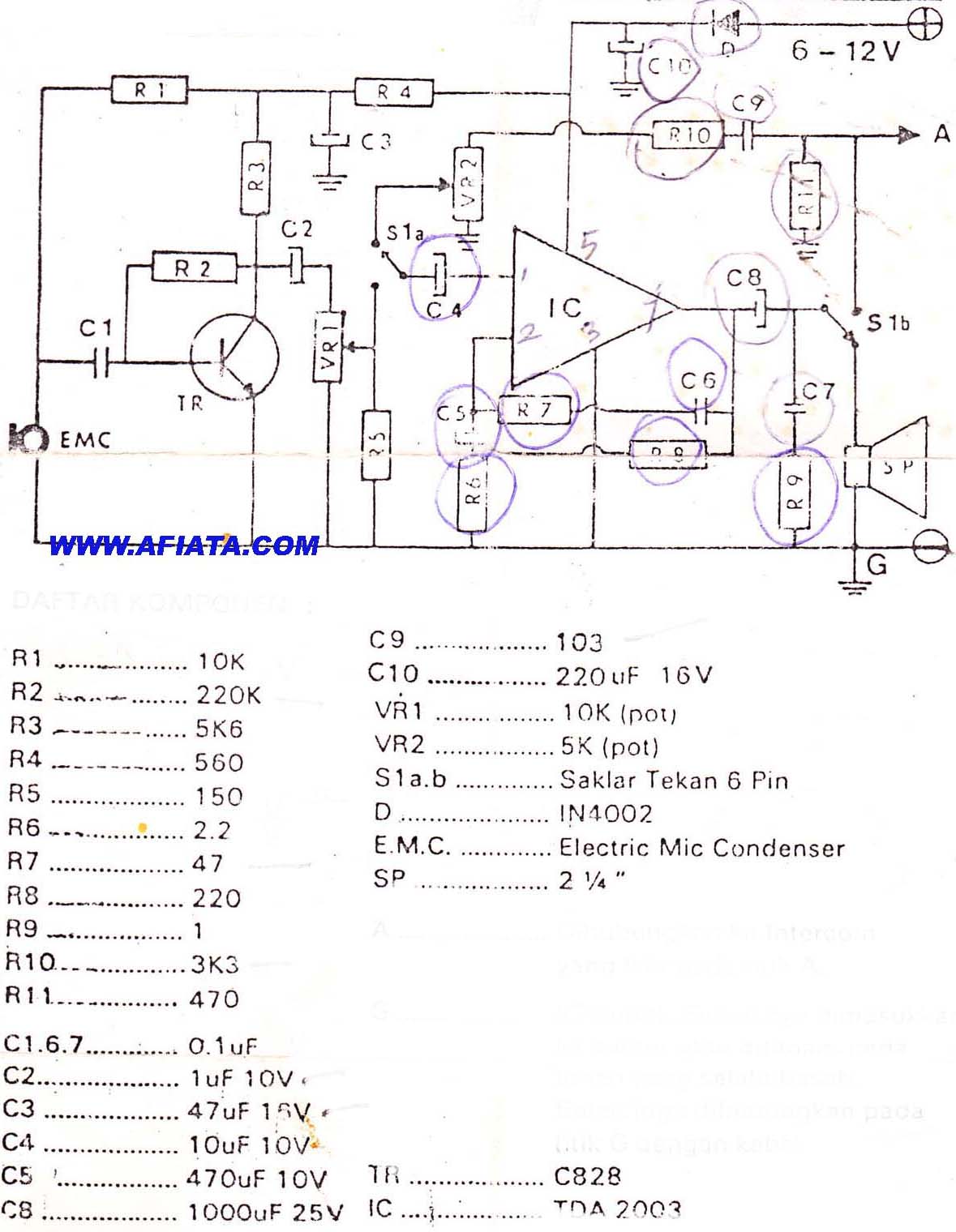
DIY Intercom Circuit Full-duplex intercom circuit schematic, cable on the way to the intercom circuit. The DIY intercom circuit is designed to facilitate two-way communication using a full-duplex system. This allows simultaneous transmission and reception of audio signals, enabling clear...

This circuit utilizes a 4049 integrated circuit (IC) to control a 2N2222 switching transistor. The transistor, in turn, drives a piezo transducer known as crystal 1. The circuit design begins with the 4049 IC, which is a hex inverter capable...
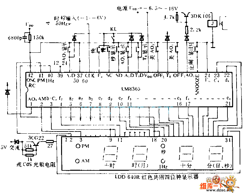
This electronic clock comprises the LM8365 and the LDD640R displays. The LM8365 can show the hour/minute and month/day. Users can set two alarm outputs, AD1 and AD2, by pressing either the 12h or 24h button. The operating voltage range...
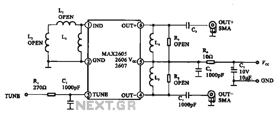
A low phase noise voltage-controlled oscillator circuit is presented, specifically integrated within the MAX2605-2609 voltage-controlled oscillator series. The circuit features a tuning voltage control terminal, allowing for adjustable oscillation frequency through a DC voltage input. The output of the...
Many applications require low-frequency signal generators that can deliver high-performance, high-resolution signals. This design idea presents a circuit that generates frequencies from 0 to 1 MHz, providing sinusoidal, triangular, and square-wave outputs with frequency resolution better than 0. A...
The device is designed to accelerate the defrosting process of fish, meat, and other foods by utilizing audio vibrations. This method allows for defrosting in warm water, significantly reducing the time required compared to conventional methods, while preserving the...