
24 Second Shot Clock

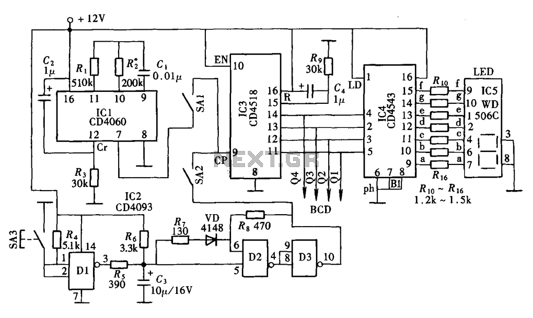
The basketball shot clock circuit is structured to provide a visual countdown for basketball games, ensuring compliance with the timing regulations of the sport. The primary component of the circuit is a microcontroller or a timer IC, such as the 555 timer, which is configured in astable mode to generate the necessary clock pulses for the countdown.
The circuit includes a 24s LOAD switch, which, when pressed alongside the Reset switch, initializes the countdown timer to 24 seconds. This dual-switch mechanism is crucial to avoid accidental resets and ensure that the timer starts from the correct value during gameplay. If the switches are not pressed simultaneously, the timer defaults to a 99-second countdown, which may be used for other game scenarios or as a safety feature.
Incorporating a pulse input from the 555 timer allows for precise timing adjustments. Calibration of the 555 timer is essential to ensure that the output pulse frequency aligns with the desired countdown intervals. This calibration process may involve adjusting resistors and capacitors in the timer circuit to achieve the correct timing characteristics.
The PAUSE switch is an important feature that allows the operator to temporarily halt the countdown. To enhance the reliability of the PAUSE function, a switch debouncer is implemented. This component prevents false triggering caused by mechanical bouncing of the switch contacts, which can lead to unintended behavior in the timer operation. The debouncer can be realized using a simple RC (resistor-capacitor) circuit or by employing a more complex digital debouncing algorithm if a microcontroller is used.
Overall, this basketball shot clock circuit design emphasizes accuracy, reliability, and user control, making it suitable for use in competitive basketball environments. Proper implementation of the components and calibration will ensure that the circuit meets the demands of the game while providing clear and accurate timekeeping.This is a circuit intended to be used in basketball shot clock.Notes:To start in 24 seconds; 24s LOAD SW and Reset SW should be push simultaneously. If not, the count will start in 99. Pulse input can be connected to 555 astable multivibrator but must be calibrated for real time clock.
The PAUSE SW must have a Switch Debouncer so that the counter will coun.. 🔗 External reference
Related Circuits
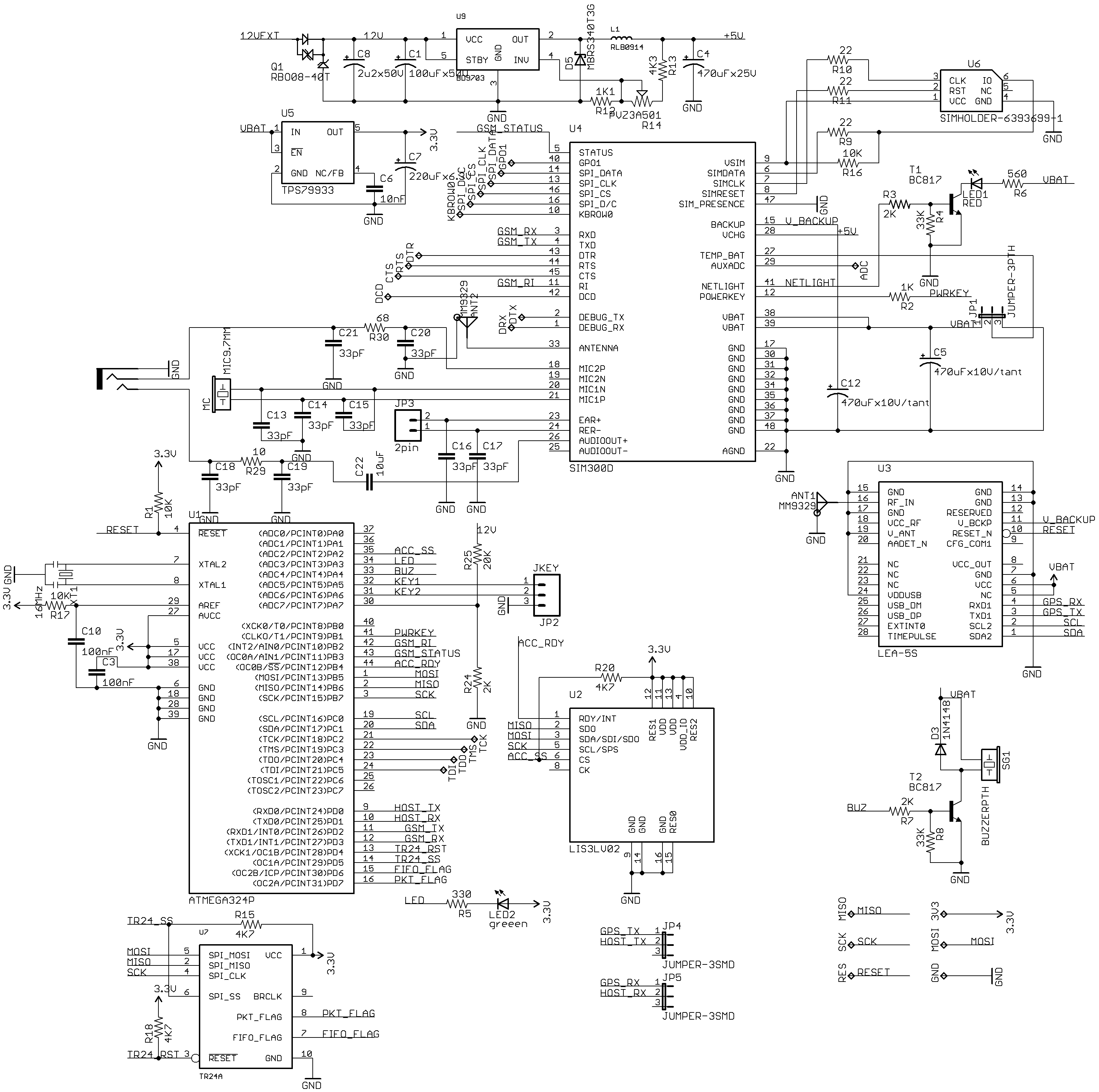
New uTracker on GE865 with a compact design. This updated version of the tracker features the SIM300DZ and EB-230/LEA-5S modules. It includes an OBD-II (ISO) sensor, an accelerometer, and an RFID reader. Additionally, a TR24 2.4GHz module is incorporated,...
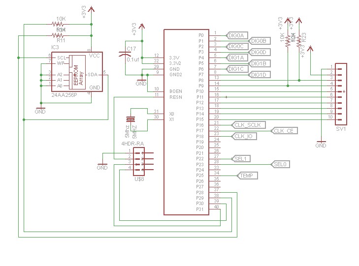
After constructing numerous Nixie Tube Clocks based on online designs, a personal design was developed. This clock utilizes IN-12 Nixie Tubes and an 8-core Propeller Microcontroller. Although the Propeller may be more powerful than necessary for this task, it...
The digital display clock signal source circuit depicted in the figure is derived from a multi-point detection control box within the actual circuit. It primarily comprises an automatic and manual pulse generator, a clock pulse generator, pulse counting elements,...
Clocks have been discussed previously in relation to their interaction with flip-flops (FFs). It is important to note that a clock generates a timing signal used to control operations. This control mechanism is evident in both D and J-K...
This month's project is based on the 4017 chip that was used in a previous project. It is advisable to review the fundamentals of the 4017 chip as presented in last month's project. The circuit has been modified slightly;...
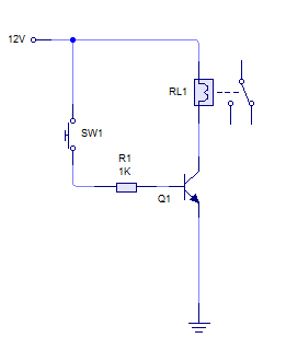
A relay is activated by grounding the low side using an NPN transistor. A pushbutton is intended to operate the transistor, thereby energizing the relay for approximately 500 milliseconds before deactivating it, while ignoring any continuous button press. Although...