
28 LED Clock Timer

The programmable clock timer circuit is designed to provide a visual representation of time using light-emitting diodes (LEDs). The core of the circuit consists of a microcontroller that manages the timing functions and controls the illumination of the LEDs. The microcontroller is programmed to keep track of the current time and to update the LED indicators accordingly.
The inner circle of twelve LEDs represents the hours, with each LED corresponding to one hour on a standard clock face. When the hour changes, the microcontroller activates the LED corresponding to the current hour while turning off the previous hour's LED. This creates a clear visual indication of the current hour.
The outer circle contains twelve additional LEDs, each representing five-minute intervals. As time progresses, the microcontroller keeps track of the minutes and activates the appropriate LED in the outer circle to indicate the current five-minute block. This allows for easy reading of the time in five-minute increments.
Furthermore, within each five-minute interval, four additional LEDs are employed to represent the specific minutes. These LEDs are activated sequentially, illuminating one LED for each minute that passes within the current five-minute block. This feature enhances the precision of the timer, allowing users to see not only the hour and five-minute intervals but also the exact minute.
Power for the circuit can be supplied by a standard DC power source, and appropriate voltage regulation should be implemented to ensure the safe operation of the microcontroller and LEDs. Resistors are also necessary to limit the current flowing through each LED, preventing damage and ensuring longevity.
In summary, this programmable clock timer circuit offers an effective and visually appealing method for displaying time through the use of multiple LEDs, providing a comprehensive overview of hours, five-minute intervals, and minute details. The design is suitable for various applications, including educational tools, decorative clocks, or timers in electronic projects.This is a programmable clock timer circuit that uses individual LEDs to indicate hours and minutes. 12 LEDs can be arranged in a circle to represent the 12 hours of a clock face and an additional 12 LEDs can be arranged in an outer circle to indicate 5 minute intervals within the hour. 4 additional LEDs are used to indicate 1 to 4 minutes of time within each 5 minute interval 🔗 External reference
Related Circuits
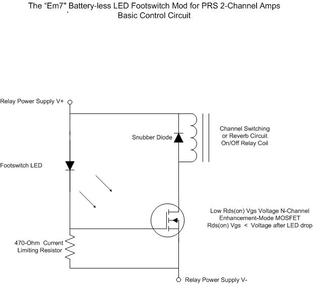
For individuals seeking LED-based footswitching without the inconvenience of battery installation, a battery-less LED-based footswitch modification is being developed for 2-channel amplifiers. This solution is designed to work with the existing TRS jack and footswitch, and it will involve...
The circuit utilizes a quad voltage comparator (LM339) as a basic bar graph meter to display the charge status of a 12-volt lead-acid battery. A 5-volt reference voltage is applied to each of the positive (+) inputs of the...
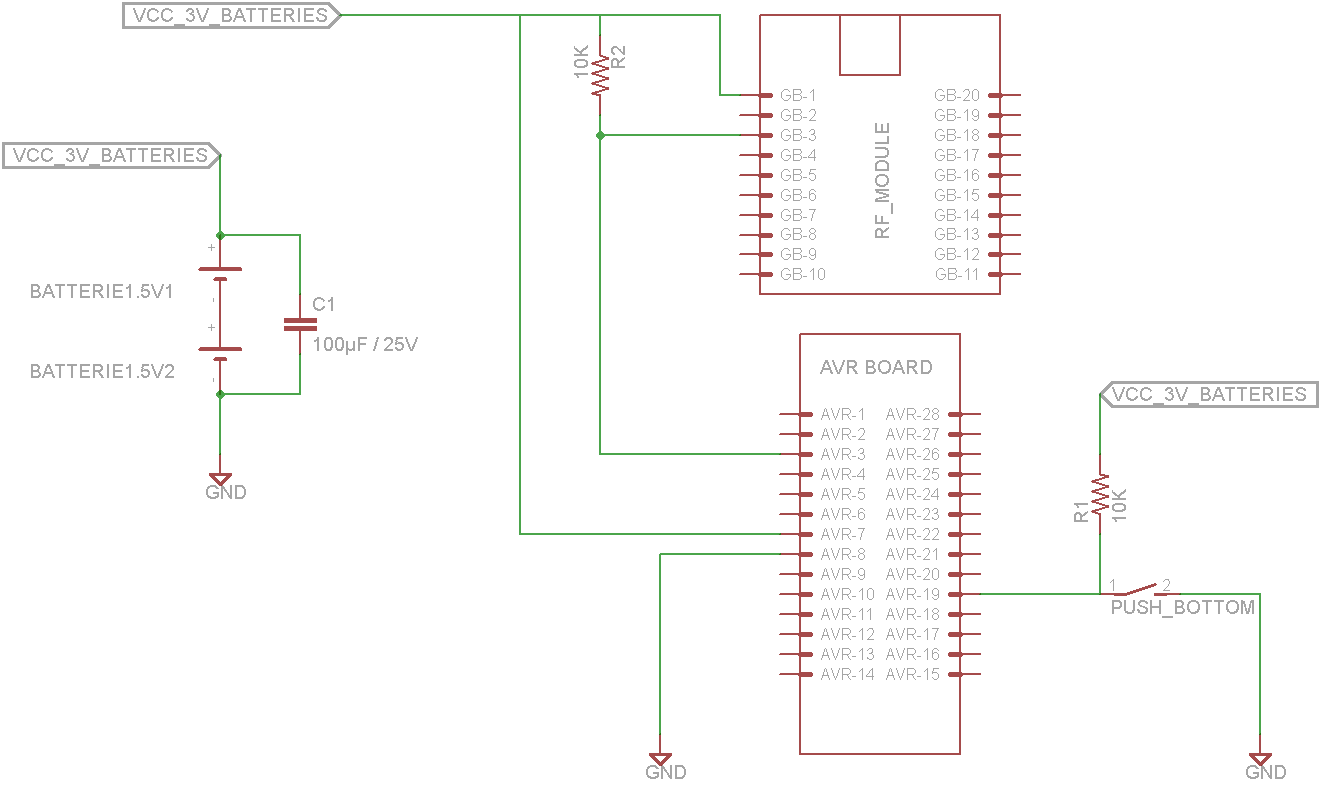
This tutorial demonstrates concepts for creating a lamp with dual actuation. The lamp can be controlled through a parallel switch or by a relay that is managed using an RF module based on the ZigBee protocol (IEEE 802.15.4). The...
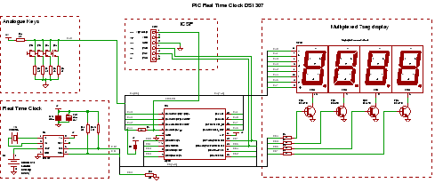
PIC RTC: A Real Time Clock IC using the DS1307 and a PIC microcontroller. This PIC project utilizes an I2C Real Time Clock chip and a display to create a four-digit standard desk clock. The described project incorporates a DS1307...
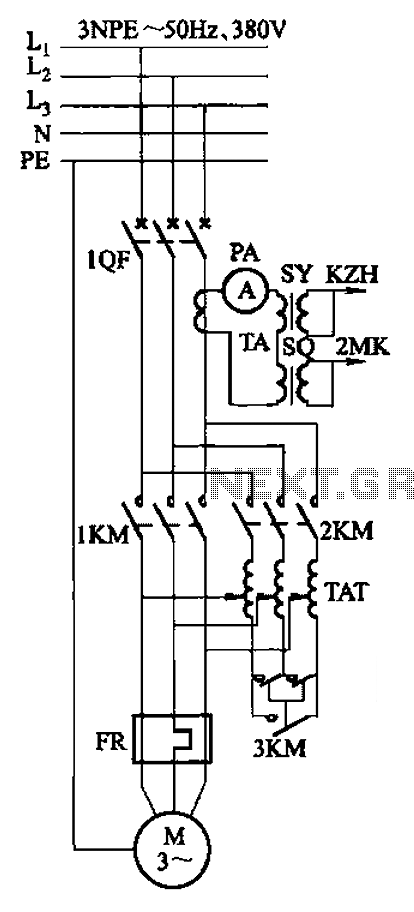
Autotransformer voltage starting, with an adjustable starting time of 30-60 seconds. It includes the SDJ electrode liquid level sensor of HJ-13 type, a pump control system box of HKD-21B type, 1MK level modules adopted by HKG-1SG type, 2MK start...
This LED flasher circuit utilizes a 555 integrated circuit (IC) and is designed to drive multiple LEDs. Notably, connecting several LEDs in series does not increase the power consumption. The LED flasher circuit based on the 555 timer IC is...