
28 LED Clock Timer

The clock circuit operates effectively by leveraging both digital and analog components, ensuring accurate time representation and control of LED indicators. The arrangement of LEDs in a circular format provides a clear visual indication of time, while the binary counter and decoder setup allows for precise counting and timing functions. The use of a center-tapped transformer ensures stable voltage regulation, and the inclusion of zener diodes helps maintain a consistent supply voltage for the logic circuits. The circuit's design allows for flexibility in programming time intervals, which is essential for applications requiring automated control based on specific timing events. The manual override feature enhances usability, providing immediate control over the relay without waiting for automated sequences. Overall, this circuit design is a robust solution for timekeeping and control applications, integrating various electronic components to achieve reliable performance.can be arranged in a circle to represent the 12 hours of a clock face and an additional 12 LEDs can be arranged in an outer circle to indicate 5 minute intervals within the hour. 4 additional LEDs are used to indicate 1 to 4 minutes of time within each 5 minute interval. The circuit is powered from a small 12. 6 volt center tapped line transformer and the 60 cycle line frequency is used for the time base. The transformer is connected in a full wave, center tapped configuration which produces about 8. 5 volts unregulated DC. A 47 ohm resistor and 5. 1 volt, 1 watt zener regulate the supply for the 74HCT circuits. A 14 stage 74HCT4020 binary counter and two NAND gates are used to divide the line frequency by 3600 producing a one minute pulse which is used to reset the counter and advance the 4017 decade counter. The decade counter counts the minutes from 0 to 4 and resets on the fifth count or every 5 minutes which advances one section of a dual 4 bit binary counter (74HCT393).
The 4 bits of this counter are then decoded into one of 12 outputs by two 74HCT138 (3 line to 8 line) decoder circuits. The most significant bit is used in conjunction with an inverter to select the appropriate decoder. During the first eight counts, the low state of the MSB is inverted to supply a high level to enable the decoder that drives the first 8 LEDs.
During counts 9 to 12, the MSB will be high and will select the decoder that drives the remaining 4 LEDs while disabling the other decoder. The decoded outputs are low when selected and the 12 LEDs are connected common anode with a 330 ohm current limiting resistor to the +5 volt supply.
The 5th output of the second decoder (pin 11) is used to reset the binary counter so that it counts to 11 and then resets to zero on the 12th count. A high reset level is required for the 393 counters, so the low output from the last decoder stage (pin 11) is inverted with one section of a 74HCT14 hex Schmitt trigger inverter circuit.
A 10K resistor and 0. 1uF cap are used to extend the reset time, ensuring the counter receives a reset signal which is much longer than the minimum time required. The reset signal is also connected to the clock input (pin 13) of the second 4 bit counter (1/2 74HCT393) which advances the hour LEDs and resets on the 12th hour in a similar manner.
Setting the correct time is accomplished with two manual push buttons which feed the Q4 stage (pin 7) of the 4020 counter to the minute and hour reset circuits which advance the counters at 3. 75 counts per second. A slower rate can be obtained by using the Q5 or Q6 stages. For test purposes, you can use Q1 (pin 9) which will advance the minutes at 30 per second. The time interval circuit (shown below the clock) consists of a SET/RESET flipflop made from the two remaining NAND gates (74HCT00).
The desired time interval is programmed by connecting the anodes of the six diodes labeled start, stop and AM/PM to the appropriate decoder outputs. For example, to turn the relay on at 7:05AM and turn it off at 8:05AM, you would connect one of the diodes from the start section to the cathode of the LED that represents 7 hours, the second diode to the LED cathode that represents 5 minutes and the third diode to the AM line of the CD4013.
The stop time is programmed in the same manner. Two additional push buttons are used to manually open and close the relay. The low start and stop signals at the common cathode connections are capacitively coupled to the NAND gates so that the manual push buttons can override the 5 minute time duration. That way, you can immediately reset the relay without waiting 5 minutes for the start signal to go away.
The two power supply rectifier diodes are 1N400X variety and the switching diodes are 1N914 or 4148s but any general purpose diodes can be used. 0. 1 u 🔗 External reference
Related Circuits
This project provides a simple temperature-controlled fan. If the difference between the actual temperature and the user-defined temperature is significant, the fan will operate. The temperature-controlled fan circuit utilizes a temperature sensor, a microcontroller, and a fan motor to regulate...
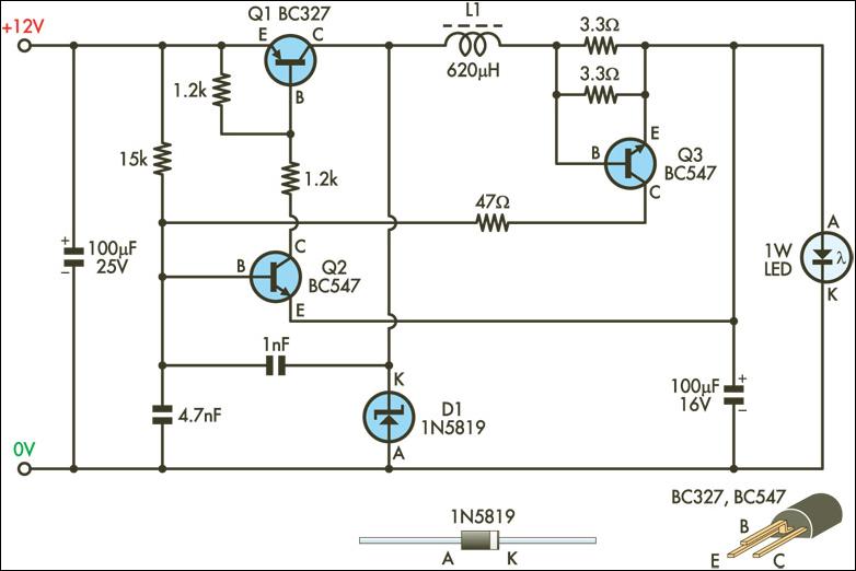
This circuit is designed to drive 1W LEDs that are commonly available. Their non-linear voltage to current relationship and variation in forward voltage with temperature necessitate the use of a 350mA constant-current power source as provided by this supply....
U1 is the 3817 integrated circuit, capable of directly driving the display. It can show time in either 12-hour or 24-hour format, schedule alarm sounds, and automatically turn on the radio at specified times. The display utilizes the FND500...
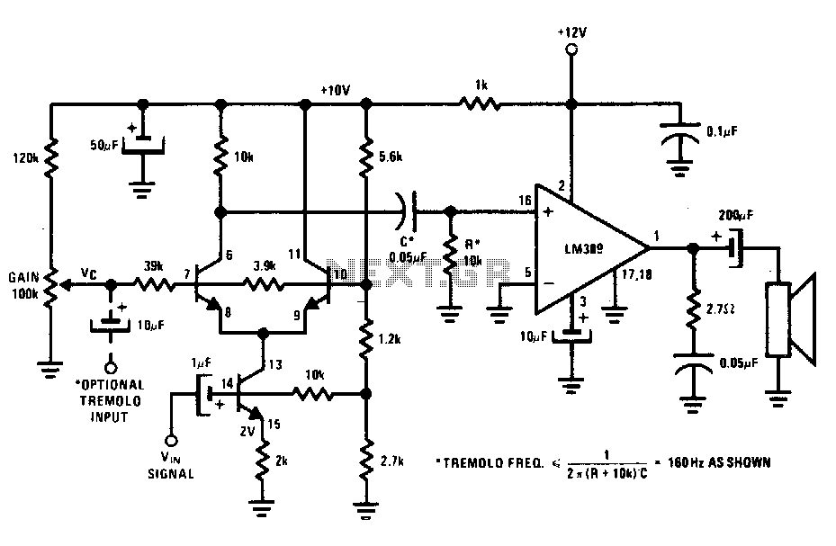
The transistors create a differential pair with an active current-source tail. This configuration, referred to as a variable-transconductance multiplier, produces an output that is proportional to the product of the two input signals. The multiplication effect arises from the...
A dimmer for individual LED bulbs. LEDs (light emitting diodes) are very sensitive components; exceeding their rated current or voltage can drastically reduce their lifespan from over 50,000 hours to mere microseconds. LEDs are current-driven, meaning that the intensity...

A Countdown Timer Circuit is a project submitted by a group of students for their ECE 130 - Computer Application class on August 31, 2006, at the University of St. La Salle, Philippines. The seven-segment decoder is utilized in...