
1W LED Driver

This circuit is an efficient solution for driving 1W LEDs, which require a stable current source due to their unique electrical characteristics. The design functions as a buck converter, utilizing Q1 as the primary switching transistor to regulate the output current. The inductor L1 plays a critical role in energy storage, while diode D1 ensures current flows in the correct direction to the output capacitor, smoothing the output voltage.
The oscillator formed by Q2 and its base circuit is essential for controlling the switching frequency of Q1. The inclusion of a 1nF capacitor for positive feedback is a key feature that enables the oscillation process, allowing for rapid switching and efficient energy transfer. The sensing mechanism implemented through Q3 ensures that the output current remains at the desired level of 350mA. As the output current increases, the voltage across the base-emitter resistors of Q3 rises, leading to its activation and the subsequent shutdown of Q2, thereby regulating the current flowing through Q1.
The hysteresis introduced by the resistor-capacitor combination connected to Q2's base enhances the stability of the current regulation, preventing rapid oscillations and ensuring a smooth output. The use of a salvaged toroidal inductor demonstrates an efficient approach to component selection, optimizing the circuit's performance.
Prior to connecting the 1W LED, it is crucial to adjust the output current. This can be achieved by temporarily connecting a 10Ω 5W load resistor and fine-tuning the base-emitter resistors of Q3 to attain the specified voltage across the load, ensuring safe operation of the LED once connected. This meticulous attention to detail in the circuit design and setup process is vital for optimal performance and longevity of the LEDs.This circuit is designed to drive the 1W LEDs that are now commonly available. Their non-linear voltage to current relationship and variation in forward voltage with temperature necessitates the use of a 350mA, constant-current power source as provided by this supply. In many respects, the circuit operates like a conventional step-down (buck) swit ching regulator. Transistor Q1 is the switching element, while inductor L1, diode D1 and the 100mF capacitor at the output form the energy transfer and storage elements. The pass transistor (Q1) is switch-ed by Q2, which together with the components in its base circuit, forms a simple oscillator.
A 1nF capacitor provides the positive feedback necessary for oscillation. The output current is sensed by transistor Q3 and the two parallelled resistors in its base-emitter circuit. When the current reaches about 350mA, the voltage drop across the resistors exceeds the base-emitter forward voltage of transistor Q3 (about 0.
6V), switching it on. Q3`s collector then pulls Q2`s base towards ground, switching it off, which in turn switches off the main pass transistor (Q1). The time constant of the 15kW resistor and 4. 7nF capacitor connected to Q2`s base adds hysteresis to the loop, thus ensuring regulation of the set output current.
The inductor was made from a small toroid salvaged from an old computer power supply and rewound with 75 turns of 0. 25mm enamelled copper wire, giving an inductance of about 620mH. The output current level should be trimmed before connecting your 1W LED. To do this, wire a 10W 5W resistor across the output as a load and adjust the value of one or both of the resistors in the base-emitter circuit of Q3 to get 3.
5V (maximum) across the load resistor. 🔗 External reference
Related Circuits

A small project in the second scene focuses on smoothly fading an LED in and out without using a microcontroller. Some modifications were made, including separating the transistors and changing the quality of the resistors. This is intended to...
A fluorescent tube is connected in an LC resonant circuit consisting of inductor L2 and capacitor C9. The bidirectional breakdown diode VD4 initiates the starting circuit. When AC power is applied, the gate potential of transistor VT2 increases due...
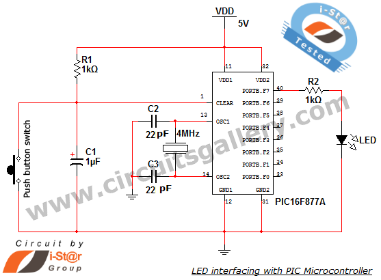
How to interface an LED with Microchip's PIC microcontroller. Connecting LEDs to a PIC microcontroller is fundamental for microcontroller development. This guide presents a simple embedded program for the PIC 16F877A to interface LEDs, making it suitable for beginners...
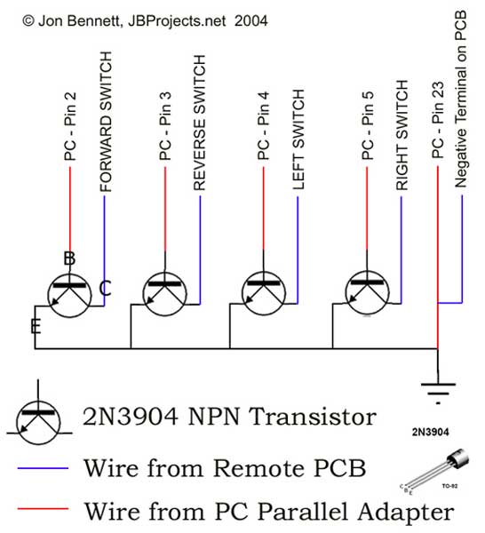
This project article was originally written in 2004 when most computers had parallel ports. This is no longer the case, so much of this information is now outdated. The Mini RC Car Project has been one of the most...
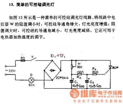
A simple silicon-controlled rectifier (SCR) dimmer circuit is depicted in Figure 13. This circuit is designed to control the brightness of lights. As the resistance in the potentiometer decreases, the conduction angle of the SCR increases, resulting in an...
This analyst is a sensitive instrument in the frequency changes and width of an acoustic signal. Thus, the brightness of the LED that turns on each moment is proportional to the signal width, while the color is proportional to...