
2Channel + Microphone Stereo Mixer

The circuit described is a compact two-channel mixer with a built-in crossfader functionality, designed for audio mixing applications. The mixer architecture allows for the integration of multiple audio sources, including stereo PHONO/line inputs and microphone channels.
The mixer comprises two identical stereo channels, each featuring two input options. The first input option is a standard PHONO input, which is equipped with a RIAA correction filter. This filter is essential for compensating the frequency response of vinyl records, ensuring that the audio output accurately reflects the original recording. The second input can accommodate line-level signals, enabling the mixer to interface with various audio devices such as CD players or digital audio workstations.
The crossfader functionality allows for seamless blending between the two channels, facilitating smooth transitions in audio playback. This is particularly beneficial in live performance settings where quick adjustments are necessary. The design of the crossfader circuit typically involves a potentiometer that adjusts the level of each channel's output, which is then mixed to produce a single output signal.
In addition to the basic two-channel configuration, the circuit can be expanded to include additional channels. This modular approach allows for the integration of stereo inputs or microphone channels, provided that the subsequent stages of the circuit are modified accordingly to accommodate the increased signal flow. Each added channel can be configured with its own gain control and EQ settings, offering flexibility in sound shaping.
The overall design emphasizes compactness and efficiency, making it suitable for both studio and live applications. The schematic should include detailed connections for power supply, grounding, and signal paths to ensure optimal performance and minimize noise interference. Proper layout considerations, such as maintaining short signal paths and adequate shielding, are crucial for achieving high-quality audio output.A lot of friends me asked to draw a more shrunk circuit 2-ch mixer, which will contain also, operation CROSSFADER. The circuits can be modified and added also other channels, repeating basic that I give. It can are added channels stereo PHONO/line or even channels microphone with proportional modification of next stages.
In the Fig.1 exist the input circuits of two channels and input of microphone channel. The two basic channels she is same between them. Thus that its go for a channel, the he is also go for the other. In each stereo channel exist two inputs, classic stereo input PHONO that is practical a correction filter RIAA and concerns the signal amplification of sound that emanates from the classic reproduction heads of classic disks LP. 🔗 External reference
Related Circuits
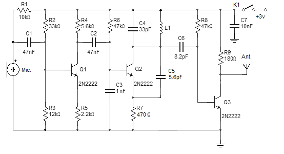
This FM wireless microphone is straightforward to construct and offers significant transmission capabilities, with a range of approximately 300 meters outdoors. Its compact component count and 3V operating voltage allow it to effectively penetrate multiple floors of an apartment...
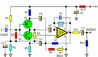
The objective of this project was to design a compact, portable mixer powered by a 9V PP3 battery while maintaining high-quality performance. The mixer consists of three primary modules that can be adjusted in number and configuration to meet...
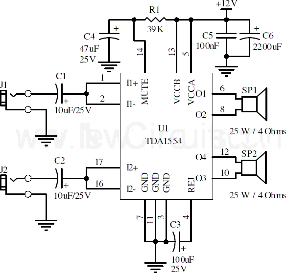
This document presents a 22-watt stereo audio power amplifier circuit diagram utilizing the TDA1554 integrated circuit from NXP Semiconductors (formerly Philips Semiconductors). The circuit is designed to effectively amplify stereo signals and is characterized by its simplicity and utility....
The composite input signal is amplified by transistor Q1 and is then connected to a high-pass filter consisting of capacitors C3 and C4, along with resistors R6 and R7. The filtered audio signal is subsequently sent to IC1, which...

The circuit is straightforward yet capable of excellent performance. It has been specifically designed for use as an amplifier for the digital sound card in a computer. Audio input can be sourced from any two-channel line-level device such as...
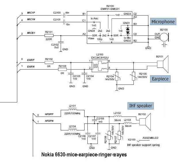
The microphone issue on the Nokia 6630 is typically attributed to several factors, including a damaged microphone, a broken circuit path, or a faulty UEM IC. If the issue arises from a broken path in the microphone circuit, it...