
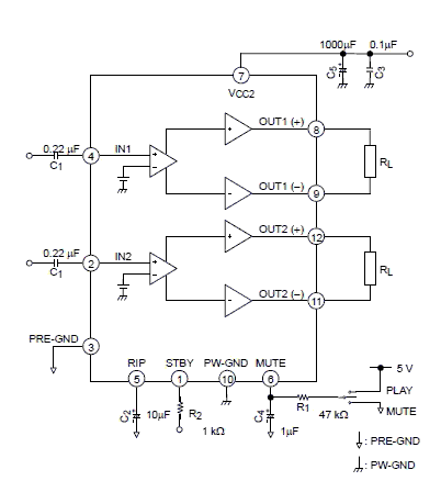
22w stereo amplifier

The TDA1554 is a dual power amplifier designed for car audio applications but is also suitable for various audio amplification tasks in home or portable audio systems. The amplifier's configuration allows for bridge operation, which enhances the output power while maintaining sound quality.
The circuit typically includes input capacitors to block any DC offset from the audio source, ensuring that only AC audio signals are amplified. The output stage connects to a speaker load, which must be carefully selected to match the amplifier's output capabilities, usually around 4 to 8 ohms.
To ensure the amplifier operates efficiently, it is essential to provide a stable 12V power supply that can deliver the required 5A current without significant voltage drop. The heatsink selected must be capable of dissipating the 28 watts of heat generated during operation, and thermal management should be considered to prevent thermal runaway conditions.
In addition to R1, other passive components such as capacitors and inductors may be included in the circuit to filter noise and stabilize the power supply. Feedback loops may also be implemented for improved linearity and reduced distortion, enhancing the overall audio quality of the amplifier.
The layout of the circuit board should minimize the length of the traces connecting the power supply and output stages to reduce inductive and resistive losses. Proper grounding techniques must be employed to avoid ground loops, which can introduce hum and noise into the audio signal.
Overall, this amplifier circuit is an effective solution for users seeking a reliable and straightforward method to amplify stereo audio signals, suitable for both novice and experienced electronics enthusiasts.Here is the 22 watt stereo audio power amplifier circuit diagram based on TDA1554 and integrated circuit from NXP semiconductors (formerly PHILIPS semiconductors). It is very simple and useful circuit for amplify the stereo signals. The circuit dissipates roughly 28 watts of heat, so a good heatsink is necessary. The chip should run cool enough to touch with the proper heatsink installed. the circuit operates at 12 Volts at about 5 Amps at full volume. Lower volumes use less current, and therefore produce less heat. R1 is also a 5% resistor. 🔗 External reference
Related Circuits
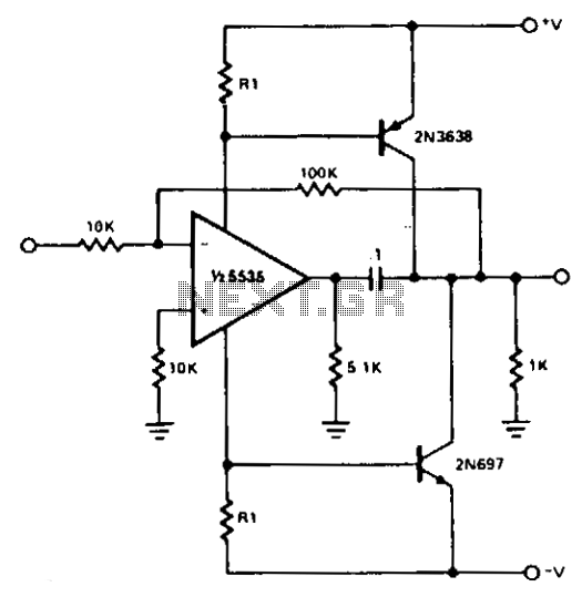
For most applications, the power provided by operational amplifiers (op amps) is adequate. However, there are instances where a greater power handling capability is required. A straightforward power booster that can drive moderate loads utilizes the NE5535 device. Other...
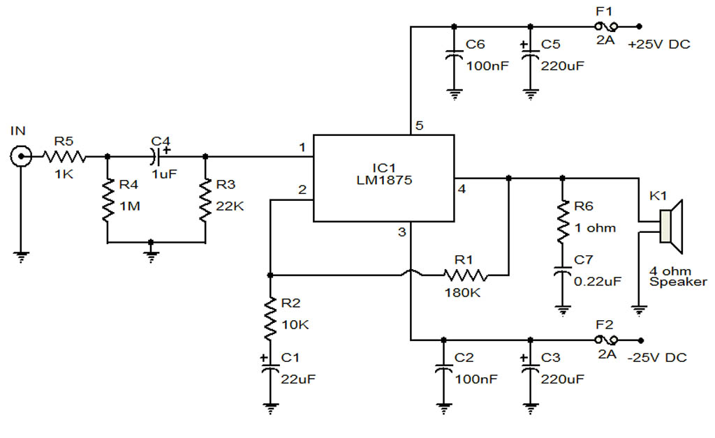
The circuit illustrates a 20-Watt audio amplifier diagram based on the LM1875 integrated circuit (IC). It is designed for use in automotive applications and provides an output power of 20 Watts. The 20-Watt audio amplifier circuit utilizing the LM1875 IC...
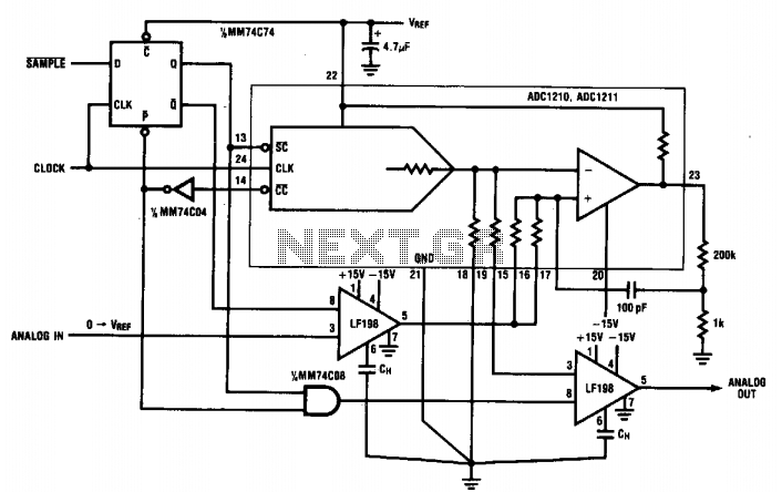
During normal hold mode, the replicated analog voltage is buffered directly through the sample-and-hold (S/H) amplifier to the output. Upon receiving a SAMPLE signal, the S/H amplifier enters hold mode, maintaining the voltage until the new analog voltage is...
This preamplifier is designed to interface with CD players, tuners, tape recorders, and similar devices, providing an AC voltage gain of 4 to drive less sensitive power amplifiers. Given that modern Hi-Fi home equipment often comes with small loudspeaker...
Using the TB2922HQ audio power IC can be designed a very simple and high efficiency power audio amplifier electronic project. TB2922HQ is 2ch BTL audio amplifier for TV or home audio applications. It includes and the pure complementary P-ch...
A popular project among microcontroller enthusiasts is to build a radio-controlled clock. Tiny receiver boards are available, equipped with a pre-tuned ferrite antenna that receives and demodulates the DCF77 time signal broadcast from Mainflingen in Germany. DCF77 has an...