
2Hz unsteady pulse single circuit diagram

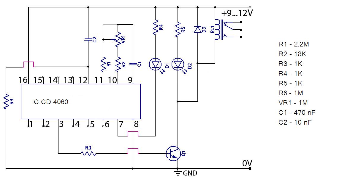
The described capacitive circuit operates with a low duty cycle, which is advantageous for applications requiring minimal power consumption. The duty cycle, defined as the ratio of the time the circuit is active to the total time period, is set between 1% and 10%. This low duty cycle allows the circuit to conserve battery life, making it suitable for long-term monitoring applications, such as studying animal physiology.
The circuit features a current draw of 50 mA during operation, with a peak battery current consumption of 1 A. This discrepancy indicates that the circuit is designed to operate intermittently, allowing for efficient energy use. The use of resistors and capacitors in the circuit design is critical for timing control. Resistor R4 in conjunction with capacitor C determines the duration of the 'on' time, effectively controlling how long the circuit remains active during each pulse. Conversely, resistor R1 and capacitor C are responsible for the 'off' time, dictating how long the circuit remains inactive before the next pulse.
The pulsing frequency of the circuit is set to twice per second, or 0.5 Hz. This frequency is particularly useful for physiological measurements, such as monitoring animal temperature and heart rate. The choice of this frequency allows for sufficient data collection intervals while minimizing the impact on the subject being monitored.
The overall design of this capacitive circuit emphasizes low power consumption and effective timing control, making it a practical solution for continuous monitoring in biological studies. The integration of resistors and capacitors provides a simple yet effective means to manage the circuit's operational states, ensuring reliable performance in its intended applications. Capacitive circuit duty cycle is very low, in the range of 1-10%. When the current is only 50mA, the battery current consumption is only 1 A. R4 and C control the opening time, and R1 and C control turn-off time. Circuit pulse twice per second, can be used to study animal temperature and heart rate.
Related Circuits
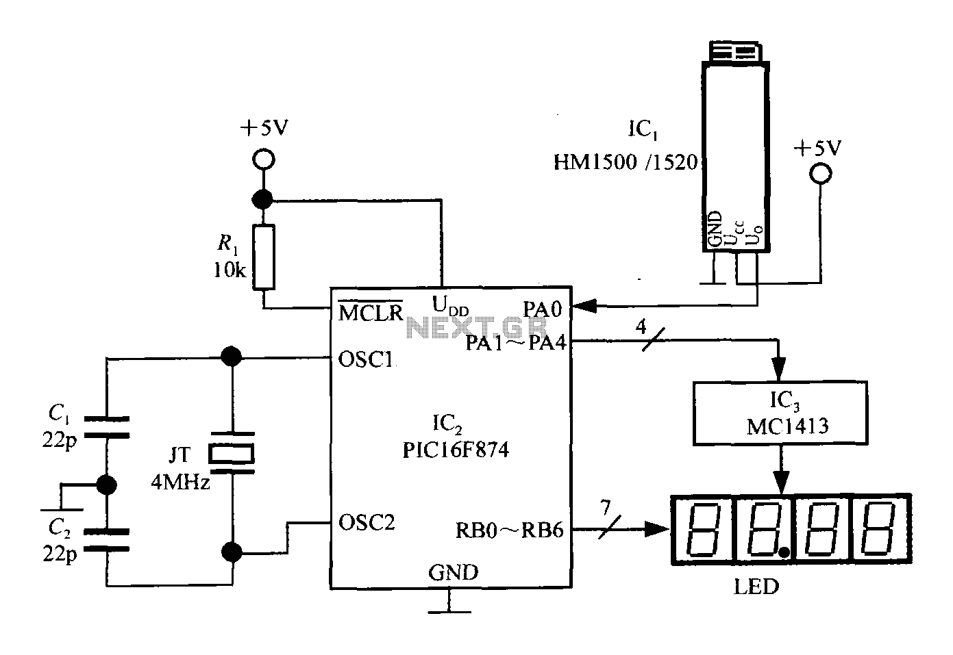
An intelligent humidity meter circuit utilizing the HM1500/1520 humidity sensor and a microcontroller configuration. The circuit operates on a +5V power supply and incorporates four common cathode LED digital displays. It employs three integrated circuits: IC1 is the HM1500/1520...
Hello everyone, please examine this circuit. I constructed it recently, but it is not functioning. I have verified all connections and components, and everything appears to be in order. However, when I power it on... The circuit in question appears...
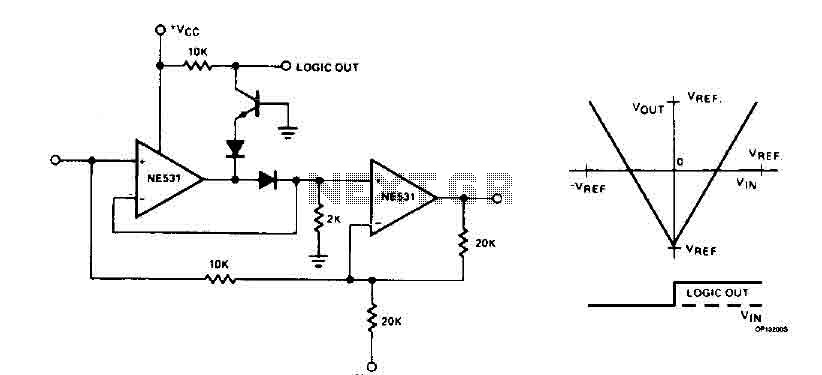
The cyclic converter is composed of a series of identical stages, each stage detecting the polarity of the input. The reference voltage, V_REF, is subtracted from the double entry, and the remaining value is processed if the polarity is...
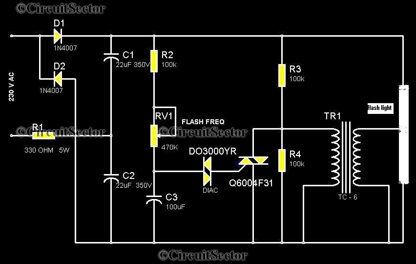
This circuit is a strobe light that allows for adjustable flashing rates. It utilizes a flash tube commonly found in cameras. In standard cameras, the flash may take ten to twenty seconds to recharge. However, this circuit enables the...
The MAX1896, MAX1973, and MAX8863 are integrated circuits that provide output voltages of 5V at 225mA, 1.8V at 220mA, and 3.3V at 60mA, sourced from a USB port. USB devices typically draw power with a voltage range of 4.5V...
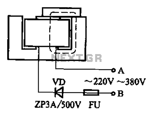
After some minor loss of field magnets, they can be re-magnetized using a homemade method. A scrap of exchanges and contacts, as well as other models like CJ10-60 ~ 15, can be utilized. The circuit operates at 0A (compatible...