
Cyclic A/D converter circuit

The cyclic converter operates by utilizing a modular design where each stage is responsible for determining the input signal's polarity. This detection is crucial for ensuring that the subsequent processing of the signal is accurate. When the input polarity is confirmed, the circuit performs a subtraction operation where the reference voltage (V_REF) is taken away from the doubled input value. This results in a modified signal that reflects the difference, which is then rectified using a full-wave rectification method. Full-wave rectification is essential as it allows for the conversion of both halves of the input waveform into a usable output, thus improving the efficiency of the signal processing.
The doubling of the difference between V_IN and V_REF enhances the sensitivity of the converter, allowing it to detect smaller changes in the input signal. The output of the converter is then formed into a gray code representation, which is a binary numeral system where two successive values differ in only one bit. This characteristic is particularly useful in applications requiring minimal error during the transition between values, as it reduces the chances of misreading the input due to simultaneous changes in multiple bits.
In practical applications, the NE531 devices are employed within the circuit to facilitate the necessary operations of voltage detection and processing. These devices are known for their precision and reliability, contributing to the overall performance of the cyclic converter. The combination of multiple stages, rectification, and the use of advanced components allows for high-accuracy voltage measurements and conversions, making this circuit suitable for various electronic applications where precise analog-to-digital conversion is required.The cyclic converter consists of a chain of identical stages, each of which detects the polarity of the input. Step V REF then subtracted from the double entry and the rest if the polarity is correct. The signal is full wave rectified and the rest of V IN - V REF is doubled. A string of these steps provides the equivalent gray code input voltage digital form related to the magnitude of V REF 'accuracy with high potential, the circuit using NE531 devices installed.
Related Circuits
The objective is to enhance information transmission through the distribution of articles. Please contact us via email at [email protected] within 15 days if there are any issues related to article content, copyright, or other concerns. Prompt deletion will occur...
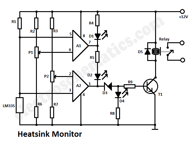
This heatsink temperature monitor circuit uses three LEDs to signal when the temperature exceeds two boundary levels. When the heatsink temperature is below 50 degrees... This heatsink temperature monitor circuit is designed to provide visual indications of temperature levels using...
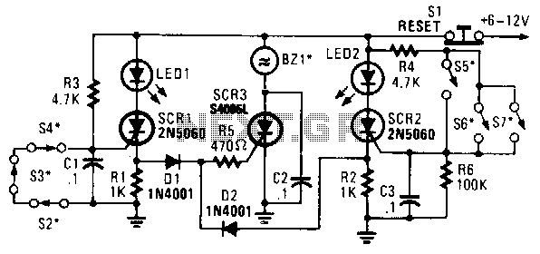
In this circuit, a low-powered silicon-controlled rectifier (SCR) is utilized to trigger a higher-powered SCR. When a switch is opened (S2, S3, S4) or closed (S5, S6, S7), either SCR1 or SCR2 is activated. This action subsequently triggers SCR3...
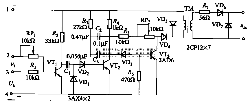
The circuit is designed for inductive loads, specifically within a thyristor power unit, such as a three-phase step-down DC motor speed control and other applications. It is capable of delivering sufficient output power to trigger a thyristor rated at...
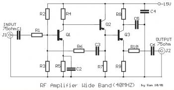
This is a 40 MHz RF amplifier circuit. The sensitivity of a receiver can be significantly enhanced by integrating this circuit between the receiver and the antenna. The amplifier does not utilize resonant circuits and is suitable for both...
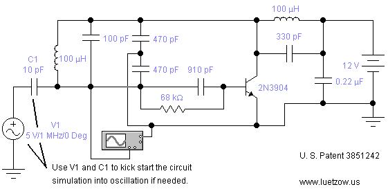
The oscillator circuits presented on this page are derived from expired or non-maintained U.S. Patents. All circuits are formatted for "Electronic Workbench 5.12" or "Multisim 7" circuit simulation software. A note regarding SPICE simulation of electronic oscillator circuits: all...