
2N4401-2N4403 Connection Diagram

The project involves the integration of a microcontroller, which serves as the central processing unit for the robot. This microcontroller is programmed with specific software that enables it to interpret commands received from a universal remote control. The use of a universal remote allows for flexible control options, making it user-friendly and accessible for various applications.
The microcontroller can be interfaced with several peripheral components, including motor drivers that control the movement of the robot. These motor drivers receive signals from the microcontroller and adjust the power supplied to the motors, allowing for precise control over the robot's motion. Additionally, sensors can be incorporated into the design to provide feedback to the microcontroller, enabling the robot to navigate its environment autonomously or semi-autonomously.
Power management is also a crucial aspect of this project. A suitable power supply must be chosen to ensure that the microcontroller and all connected components operate efficiently. Battery options should be considered, along with voltage regulators if necessary, to provide stable power to the system.
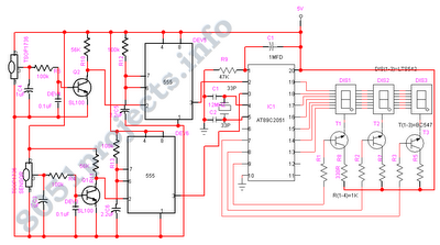
In summary, this project exemplifies the application of microcontroller technology in robotics, leveraging software programming and remote control capabilities to create an interactive and functional robotic system. The design can be further enhanced by integrating additional features such as obstacle detection, automated navigation, and advanced control algorithms to expand its operational capabilities.This project uses a microcontroller programmed with software that is posted on the Gerns-back BBS at 516-293-2283 as part of RUNABOUT. ZIP. The robot can be controlled via a universal remote control. 🔗 External reference
Related Circuits
During the process of organizing computer files, a schematic was discovered that was utilized in the initial phase of USB LED Matrix development. It is believed that this schematic could be beneficial to others. The schematic in question pertains to...

The application circuit operates the device as illustrated below, allowing for intermittent lighting in specific situations (e.g., during surgery). It utilizes an LCE module for blackout emergency lighting, which activates automatically after a power failure, ensuring uninterrupted illumination. In...
The digital visitor counter is a reliable circuit designed to accurately count the number of persons or visitors in a room. When an individual enters the room, the counter increments by one, and when someone leaves, the counter decrements...
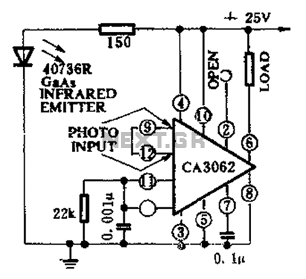
CA3062 is a combined photodetector and power amplifier that responds to the optical signal generated by the on/off output. The integrated circuit's transistor output saturation should be either on or off to prevent temperature rise in the silicon. When...
The two unspecified polarized capacitors (one directly above the transformer and one directly to the right of the transformer) are actually each a pair of 470 µF capacitors in parallel (for a total of four 470 µF capacitors). These...
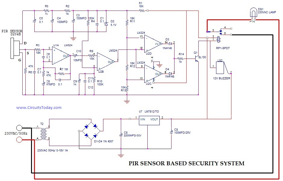
PIR (Passive Infrared Radial) Sensor-Based Security System, circuit diagram, working, applications. The PIR (Passive Infrared) sensor-based security system is designed to detect motion by measuring changes in infrared radiation emitted by objects in its vicinity, particularly warm bodies such as...