
Minimal PIC18 USB connection schematic

The schematic in question pertains to a USB LED Matrix, a device that utilizes an array of light-emitting diodes (LEDs) to create visual displays controlled via a USB interface. The design typically includes a microcontroller to manage the LED operation, allowing for dynamic content display.
The matrix is usually constructed with a grid layout, where each LED is individually addressable. This enables the creation of various patterns and animations by controlling the intensity and color of each LED. The microcontroller is programmed to interpret data received through the USB connection, which may come from a computer or other USB-enabled device.
Power management is a critical aspect of the design, as the LED matrix must operate efficiently to prevent overheating and ensure longevity. A voltage regulator may be included to maintain a stable power supply to the LEDs and microcontroller. Additionally, current-limiting resistors are often employed to prevent excess current from damaging the LEDs.
The schematic may also incorporate various input/output (I/O) connections, allowing for the integration of additional features such as buttons for user interaction or sensors for environmental feedback. This versatility enhances the usability of the LED matrix in different applications, ranging from decorative displays to functional indicators.
Overall, the USB LED Matrix schematic serves as a foundational blueprint for those interested in developing their own LED display projects, offering insights into the necessary components and their interconnections.While cleaning up my computer files I stumbled over this schematic, which I used in the early stage of the USB LED Matrix development, and I thought it might be usefull to others. 🔗 External reference
Related Circuits
The unit is powered directly from the 120 volt AC line, with no power transformers. Filaments are wired in series, with the total adding up to 117 volts (35 + 35 + 35 + 12). The 35W4 forms a...

The circuit diagram for the Desheng 89701 type radio, a compact shortwave receiver, is provided below. The Desheng 89701 is designed for shortwave reception, making it suitable for capturing a variety of radio frequencies across the shortwave band. The circuit...
With a DPDT switch, I can switch the two data lines. I tried connecting the shields from the two computers together, the grounds two computers together, switching the D+ and D- lines with the DPDT switch, and leaving the...
The system employs an optical fingerprint sensor utilizing the ARM Cortex M3 core, specifically the STMicroelectronics 32-bit high-performance microcontroller STM32F205RE. It incorporates a function body composition that utilizes the Sobel edge detection operator, Gabor filtering, image binarization, and various...
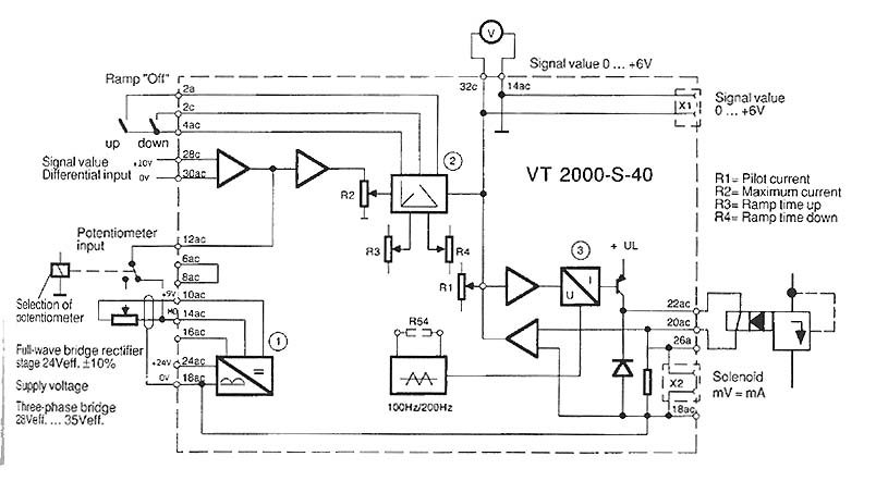
The function is to adjust the time constant associated with a capacitor, thereby influencing the ramp time. The components involved include a transistor, capacitor, and resistor. The circuit described is designed to modify the time constant in an RC (resistor-capacitor)...
This is a 5V to 12V DC-DC step-up (boost) converter circuit that is particularly suitable for USB-powered applications. Initially, a USB port has two current supply modes. Before detecting the connected device, it supplies a maximum of 100mA to...