
2W RF Amplifier with MOSFET LF2810A

The 2W RF amplifier circuit is designed to enhance the power level of radio frequency signals, making it suitable for various applications in communication systems. The LF2810A MOSFET is a key component, chosen for its high efficiency and capability to operate at microwave frequencies. This device features a low gate-source capacitance, which allows for faster switching speeds, making it ideal for RF amplification.
The circuit typically includes a matching network at the input and output stages to ensure maximum power transfer and minimize reflections. The input matching network is designed to match the source impedance to the gate of the MOSFET, while the output matching network optimizes the load impedance for the drain. This configuration helps to achieve a high gain and a low noise figure, which are critical parameters in RF applications.
Power supply decoupling capacitors are often included in the design to stabilize the voltage supplied to the MOSFET and to filter out any high-frequency noise that may affect the amplifier's performance. Additionally, thermal management components, such as heat sinks, may be employed to dissipate heat generated during operation, ensuring reliable performance over extended periods.
The overall layout of the microstrip circuit is crucial for maintaining performance at RF frequencies. Careful consideration must be given to trace widths, lengths, and the dielectric material used in the substrate to minimize losses and maintain signal integrity. Proper grounding techniques are also essential to prevent unwanted interference and ensure a stable operating environment for the amplifier.
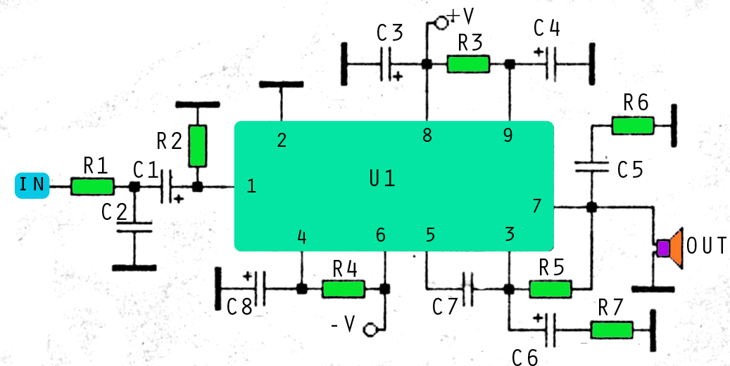
In summary, this 2W RF amplifier circuit utilizing the LF2810A MOSFET is a well-engineered solution for enhancing RF signal power, with a focus on efficiency, performance, and reliability in communication systems.This is a 2W RF amplifier circuit build with power MOSFET LF2810A. Figure A Figure A is the schematic of the microstrip single stage RF amplifier. The amplifier is based on the M/A-Com LF2810A MOSFET. The transistor is actually a watt, 2.. 🔗 External reference
Related Circuits
Here you will find a design for a headphone amplifier. The supply voltage is 12 volts. I have the circuit taken as 5 watt amplifier, but after a test showed that with a little speaker to the amplifier power...
That Circuit is a UHF TV linear amplifier for small TV transmitters with output around 100-200mW. The transistor BGQ136 comes with SOT-122 case has gain of 13dB at 800MHz. So with input 100mW you get 2W output and for...
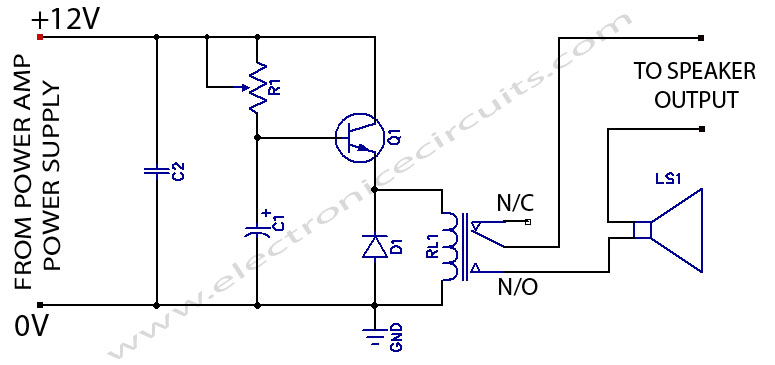
When powering on a power amplifier, a loud thump sound occurs due to a sudden heavy discharge current through the speaker. This current has the potential to damage the speaker, particularly in the case of a direct-coupled amplifier. The phenomenon...
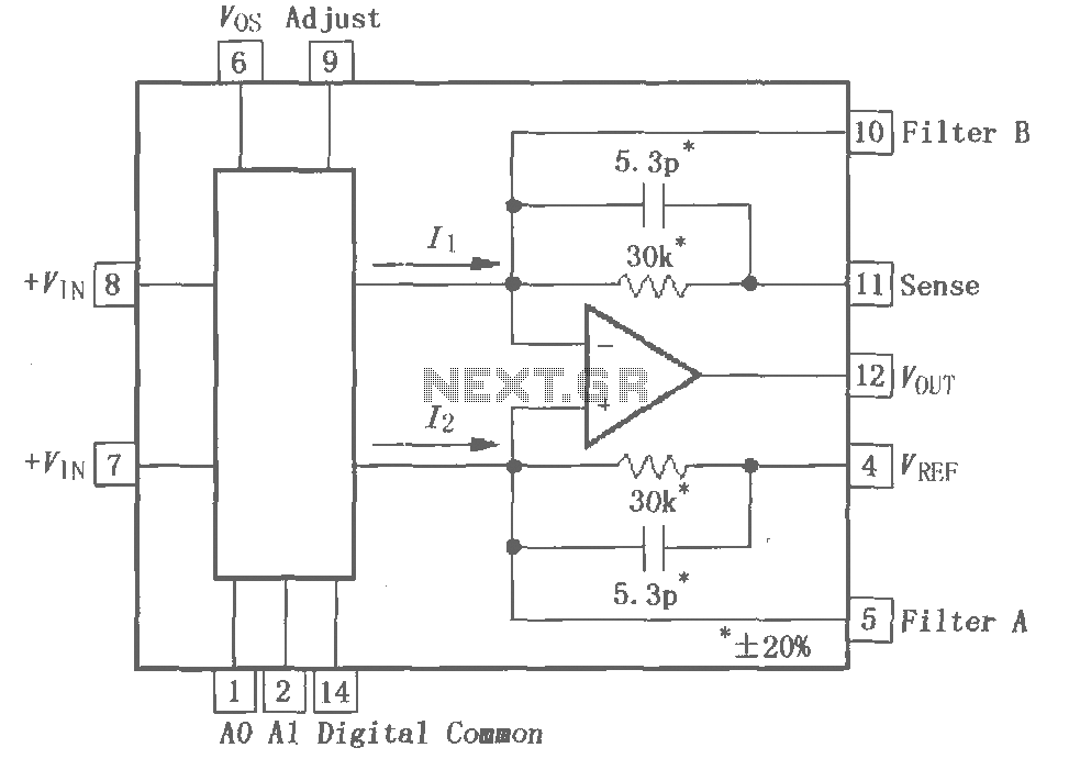
The PGA202 is a digitally controlled programmable gain amplifier with gain settings of G = 1, 10, 100, and 1000. The PGA203 offers gain settings of G = 1, 2, 4, and 8. Both amplifiers are compatible with CMOS...
This amplifier circuit utilizes three voltage levels: positive, negative, and ground, with a maximum voltage of approximately 55V DC. The circuit can accommodate several integrated circuits (ICs), including STK 030, 058, 075, 077, 078, 080, 082, 083, 084, and...
The combination of controller IC LM4651 and LM4652 Class D MOSFET power amplifier IC provides a high-efficiency solution suitable for powered speakers, subwoofers, and car amplifiers. The LM4651 is a fully integrated conventional pulse width modulator (PWM) driver, which...