
Headphone Amplifier LM741

The headphone amplifier design described utilizes a supply voltage of 12 volts and is capable of delivering an output power of approximately 5 watts. The circuit architecture is based on an operational amplifier (op-amp) LM741, which provides the initial gain stage necessary for audio amplification. The output stage consists of a complementary push-pull configuration using transistors BD139 and BD140, which enhances the current driving capability of the amplifier.
The circuit is designed to be used primarily with headphones, although it can also drive small speakers. For stereo applications, the circuit can be duplicated, requiring two identical amplifier stages. The input signal is processed through a series of resistors (R1, R2, R3, R4, R5, R6, R7, R8, and R9) that set the gain and establish the input impedance, ensuring compatibility with various audio sources.
A critical component in this design is the 1000 µF capacitor (C5), which acts as a coupling capacitor in the output stage. It blocks any DC component from reaching the headphone or speaker, allowing only the AC audio signal to pass. This capacitor's value is chosen to provide a low-frequency cutoff at approximately 40 Hz when driving a load of 4 ohms, ensuring adequate bass response.
The circuit also incorporates a bass boost feature, which can be toggled to enhance low-frequency performance, making it suitable for various audio content. The overall current consumption is approximately 50 mA, which is efficient for portable applications. The design does not require additional heat sinking for the transistors when used with headphones, indicating that the power dissipation remains within safe limits under typical operating conditions.
The parts list includes resistors of various values, capacitors with specified voltage ratings, and diodes (1N4148) for signal protection. The use of a linear potentiometer (P1) allows for adjustable gain, providing flexibility in audio output levels. This headphone amplifier design is suitable for applications requiring a compact and efficient audio amplification solution.Here you will find a design for a headphone amplifier. The supply voltage is 12 volts. I have the circuit taken as 5 watt amplifier, but after a test showed that with a little speaker to the amplifier power was provided. It is better to connect to a headset. If you want stereo, you need double the amp build. The circuit is constructed with a 741, behind a balanced stair comprising a BD 139 and BD 140. The voltage for the speaker in the middle of this balance tapped using a blocking capacitor, which filters the amplified signal from DC.
This capacitor has a value of 1000 uF. This provides a lowest possible frequency of 40 Hz at 4 ?. For this example, the amplifier bass boost or bass control can be switched. The current consumption of the circuit is up to approximately 50 mA. The transistors do not need to be cooled when a headset is connected. Parts List R1, R3 = 10kW R2 = 100 kOhm R4 = 1 kOhm R5 = 15 kOhm R6, R7 = 2.2 kOhm R8, R9 = 1 ? P1 = 10kW lin C1 = 100 V ?F/16 C2 = 1 V ?F/16 C3 = 22 ?F/16 V C4 = 470 pF C5 = 1000 V ?F/16 D1, D2 = 1N4148 T1 = BD139/16 T2 = BD140/16 IC1 = LM 741
🔗 External reference
Related Circuits
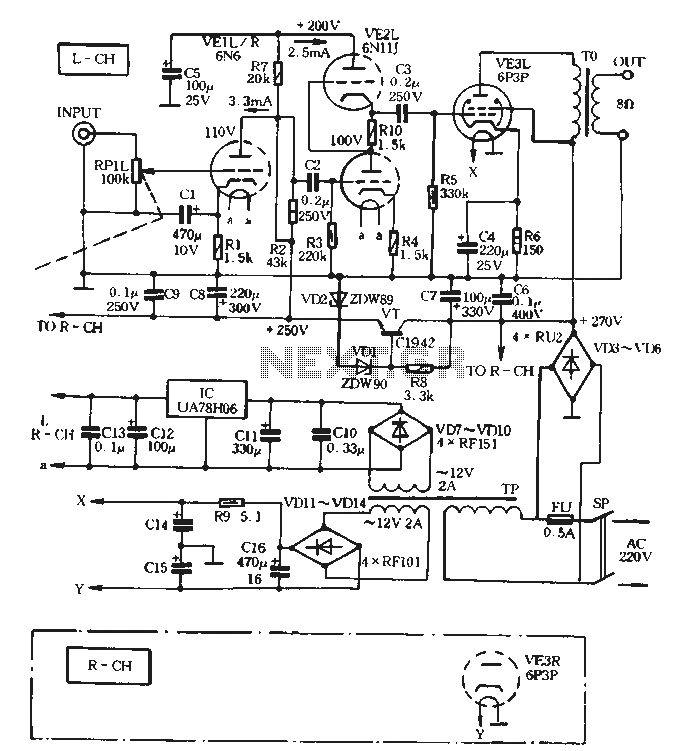
The VE1 preamplifier utilizes a low muscle, low resistance double triode 6N6 configuration, with separate halves for the left and right audio channels. The design operates within the CPI framework. It promotes the use of high-level VE2 household low...
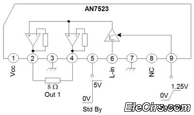
The third series of the function utilizes the same system, specifically BTL (Bridge Transformer Less). This configuration offers several advantages, including the elimination of coupling capacitors and coupling transformers. The BTL (Bridge Transformer Less) configuration is a significant advancement in...
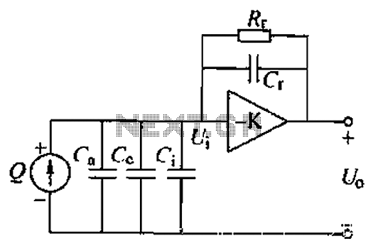
A charge amplifier is an effective device for measuring punch hits. This amplifier utilizes a negative feedback capacitor in conjunction with a high-gain operational amplifier. The amplifier operates with minimal shunt, relying primarily on the feedback capacitor's charge (q...
This is a simple Vox AC amplifier. The circuit is not very clear but is readable. The circuit in question represents a basic Vox AC amplifier. The primary function of this circuit is to amplify the input audio signals, specifically...
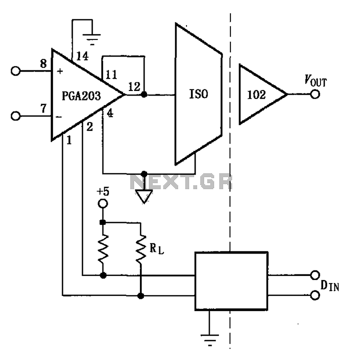
The PGA203 and isolation amplifier IS0102 form an isolated programmable gain instrumentation amplifier circuit. The PGA203 amplifies the input signal, and the output from the isolation amplifier IS0102 is VOUT. Additionally, a DIN digital optocoupler is used for the...
The aim of this design is to reproduce a Combo amplifier of the type very common in the sixties and the seventies of the past century. It is well suited as a guitar amplifier but it will do a...