
2Watt Audio Amplifier

The circuit is designed as a discrete amplifier that emphasizes simplicity and ease of assembly. By avoiding integrated circuits, the design offers a hands-on approach, appealing to hobbyists and engineers who appreciate traditional circuit-building techniques. The choice of a 12V wall adapter for power supply ensures compatibility with common power sources, making the amplifier suitable for various applications.
The bass boost feature, activated by switch SW1, enhances low-frequency response, which is particularly beneficial for applications requiring richer sound quality. However, users must be aware that engaging this feature necessitates an increase in volume control to counterbalance the inherent power loss at higher frequencies, ensuring that the output remains consistent and clear across the audio spectrum.
Resistor R9 plays a critical role in managing crossover distortion, which can adversely affect audio quality if not properly adjusted. The recommendation to set the quiescent current at 10-15 mA strikes a balance between performance and efficiency, allowing the amplifier to operate effectively while minimizing heat generation and power consumption. The inclusion of a DC current meter for measuring quiescent current provides a practical method for users to fine-tune the amplifier's performance, ensuring optimal operation.
Overall, this circuit exemplifies a classic approach to audio amplification, combining simplicity, functionality, and ease of use, making it a valuable project for those interested in exploring the fundamentals of electronic amplifiers.The circuit was deliberately designed using no ICs and in a rather old-fashioned manner in order to obtain good harmonic distortion behavior and to avoid hard to find components. The amplifier(s) can be conveniently supplied by a 12V wall plug-in adapter. Closing SW1 a bass-boost is provided but, at the same time, volume control must be increased to compensate for power loss at higher frequencies. In use, R9 should be carefully adjusted to provide minimal audible signal cross-over distortion consistent with minimal measured quiescent current consumption; a good compromise is to set the quiescent current at about 10-15 mA. To measure this current, wire a DC current meter temporarily in series with the collector of Q3. 🔗 External reference
Related Circuits
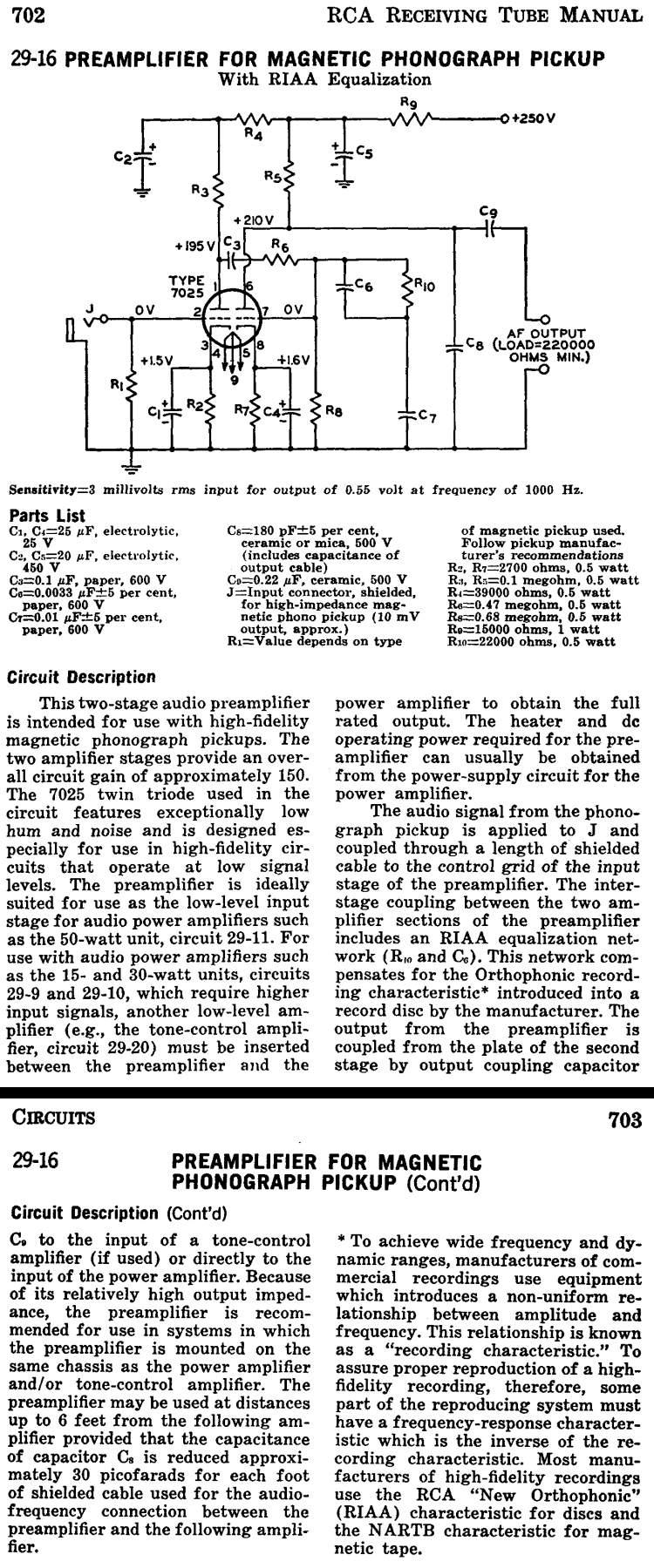
This two-stage audio preamplifier is designed for high-fidelity magnetic phonograph pickups, providing an overall gain of approximately 150. The circuit is sourced from the RCA tube receiving manual and is intended for use with the renowned RCA 7025 twin...
The 2N3819 is an n-channel JFET specifically designed for RF and mixer applications, offering very low noise, minimal distortion, and excellent high-frequency gain. Creating a PCB can be accomplished in a few straightforward steps. Begin by using PCB design...
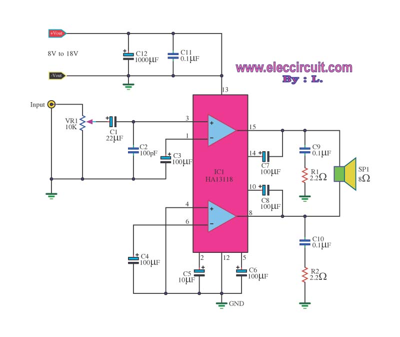
The amplifier circuit utilizes the HA13118 IC, a Hitachi component designed to deliver 18 watts of output power. This integrated circuit operates as a Class AB amplifier. The HA13118 IC is a versatile audio amplifier designed for high-fidelity applications, providing...
An RF power amplifier is a type of electronic amplifier used to convert a low-power radio-frequency signal into a larger signal of significant power, typically for driving the antenna of a transmitter. It is optimized for high efficiency, high...
The D amplifier utilizes a series fool manifold and can easily be configured as a mono output transformerless (OTL) or output capacitorless (OCL) audio power amplifier. Figure 3-12 illustrates a single-channel power output typical application wiring diagram for OTL....
The preamplifier that appears in the figure is a completely symmetrical preamplifier, from the input as the exit and it works in Class A. It does not have somebody innovation, simply it uses good solutions, in order the result...