
Symmetrical Audio Class A preamplifier

The described preamplifier is a Class A symmetrical amplifier circuit designed for high fidelity audio applications. The symmetrical design ensures that the signal is amplified equally in both positive and negative cycles, reducing distortion and improving linearity. The use of matched transistors, specifically Q1 and Q2, is crucial for maintaining thermal stability and minimizing variations in performance due to temperature changes. These transistors are ideally sourced from the same integrated circuit to ensure they share similar thermal characteristics.
The replacement of Q1 and Q2 with BC550C and BC560C transistors is a practical approach, provided that careful selection is made to ensure that the pairs are well-matched in terms of their characteristics. This matching is essential to maintain the integrity of the amplification process and to achieve optimal performance.
The circuit includes a variable resistor, TR1, which allows for the adjustment of the output offset voltage. This feature is important for eliminating any DC offset at the output, which can lead to distortion in the amplified signal. If the offset adjustment is deemed unnecessary, it can be bypassed by using two 82-ohm resistors in place of R6 and R7, simplifying the design while still ensuring stable operation.
Diodes D1 and D2 play a significant role in the circuit by providing thermal compensation for transistors Q3 and Q4. It is critical that these diodes are placed as close as possible to their respective transistors to ensure they respond to temperature changes in a synchronized manner. This arrangement helps to maintain consistent performance across varying ambient temperatures.
Furthermore, transistors Q8 through Q11 are also involved in maintaining the thermal stability of the circuit. Their arrangement and interaction with the other components are vital for achieving the desired performance characteristics of the preamplifier. Overall, this preamplifier design exemplifies effective engineering practices to achieve high-quality audio amplification with minimal distortion and maximum reliability.The preamplifier that appears in the figure is a completely symmetrical preamplifier, from the input as the exit and it works in Class A. It does not have somebody innovation, simply it uses good solutions, in order the result is what should.
Such proposal is the use transistors matched [Q1, 2], that finds in the same chip with result the thermic and other characteristics are ``perfect``. It can they are replaced by simple transistors as the BC550C and BC560C it`s enough you enter in the fatigue to matched you pairs with similar characteristics.
With the TR1 we can if it needs we regulate the Offset voltage in the exit of unit. It can however be suppressed and it`s replaced with two resistances 82 ohm in the place of R6 -7. A point that it should I accent it`s that diodes D1 and D2 it should they are placed very near in transistors Q3 and Q4 respectively, so that they have common thermic behavior. The himself should become also with transistors Q8 - Q10 and Q9 - Q11 respectively. 🔗 External reference
Related Circuits
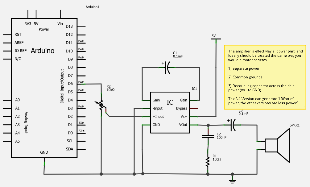
The transistor is biased in Class A, meaning that the collector current flows continuously. This current can vary, increasing or decreasing in response to the input signal. In a Class A biasing configuration, the transistor operates in the active region...
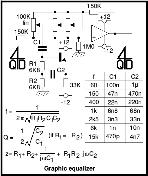
Audio graphic equalizers are very common as commercial products (for Hi-fi, car audio and stage use) but circuits for them are very rarely published. I didn't design this one but it's really very simple. The details shown are...

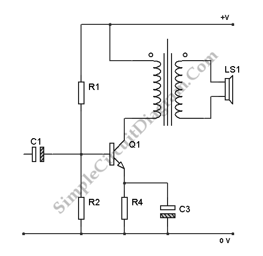
This is a low watt audio amplifier with a different technique in design. The 1.8K resistor has been connected to output of the circuit instead of VCC line. The output power of the circuit is about 250mW on an...
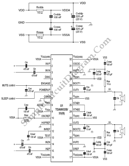
The TDA8932B/33(B) can operate with a symmetrical power supply. In this configuration, three half supply voltage buffers are disabled when powered from a symmetrical source. The TDA8932B/33(B) is a high-efficiency Class D audio amplifier designed for various audio applications. Operating...
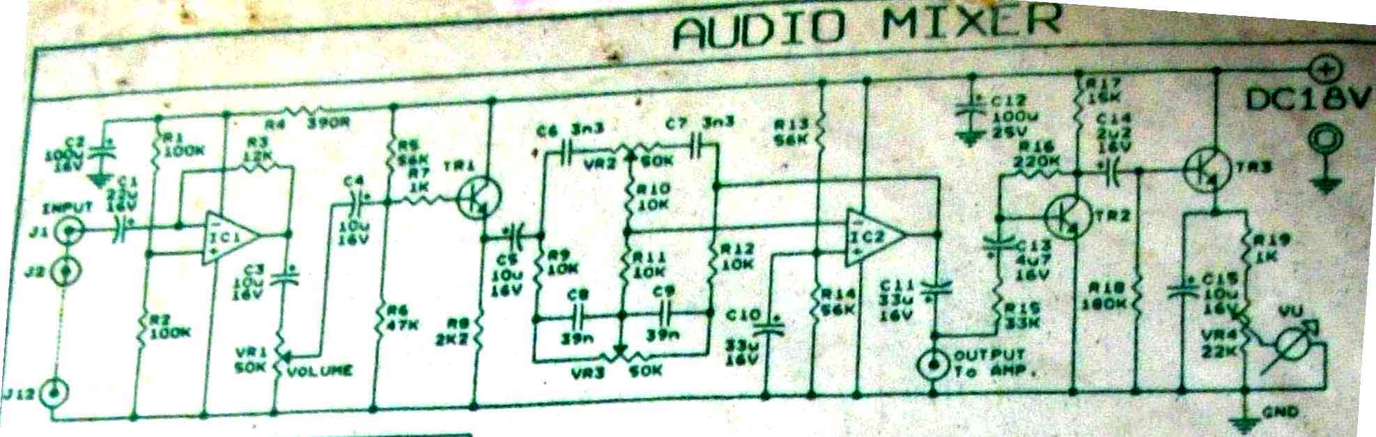
This is audio mixer circuit. The circuit is for one channel input, if you need, for example 5 channel mixer, then you need to build 5 similar circuits. The audio mixer circuit described is designed to handle a single channel...
A simple solution for enhancing sound output from a microcontroller is the LM386 series of amplifier chips, which provide high-quality audio for under one dollar. These chips can be used to create a functional MP3 docking station and serve...