
3 band equalizer circuit

The 3-band equalizer circuit employs the LM833 op-amp to create three separate filter stages, each tailored to enhance or attenuate a specific frequency range. The bass filter typically operates within the range of 20 Hz to 250 Hz, the midrange filter covers approximately 250 Hz to 4 kHz, and the treble filter is effective from 4 kHz to 20 kHz. Each filter stage can be adjusted using potentiometers, allowing for precise control over the audio output.
The circuit configuration involves using resistors and capacitors to set the cutoff frequencies for each band. The feedback network around the LM833 op-amp is designed to provide the desired gain and frequency response. For instance, the bass filter can be configured with a higher gain to amplify low frequencies, while the treble filter can be set with a lower gain to avoid distortion of high frequencies.
Power supply considerations for the LM833 op-amp should include a dual supply voltage, typically ±15 V, to ensure optimal performance. Proper decoupling capacitors should be placed close to the power pins of the op-amp to minimize power supply noise and enhance stability.
Additionally, the output of each filter stage can be mixed together using a summing amplifier configuration, allowing the user to achieve a balanced overall sound. Careful layout of the circuit board is essential to minimize interference and maintain signal integrity, particularly in high-frequency applications. Overall, this 3-band equalizer circuit provides a versatile solution for audio signal processing, enabling users to tailor their listening experience to personal preferences.This 3 band equalizer circuit is an active filter network for bass, mid and high audio ranges. It is designed around the LM833 opamp from National Semiconductors. This opamp IC has the following charactersistics: very low noise figure, wide.. 🔗 External reference
Related Circuits
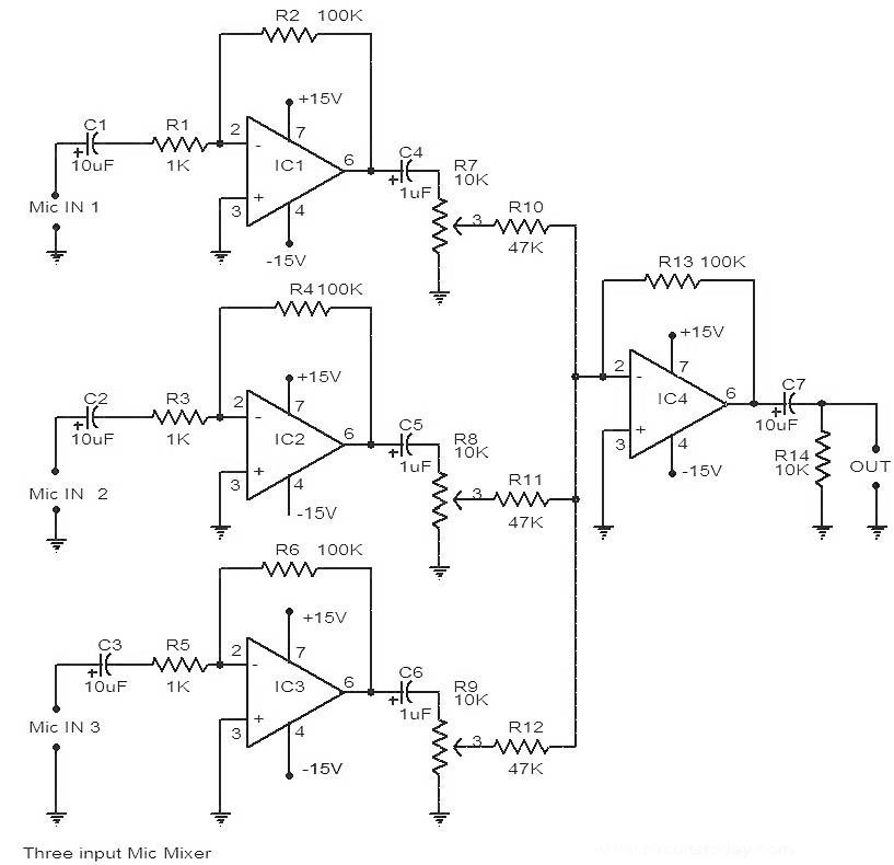
This is a circuit diagram of a 741 IC-based three-input microphone mixer circuit. A total of four 741 ICs are utilized, with IC1, IC2, and IC3 serving specific functions within the design. The circuit utilizes four operational amplifiers from the...
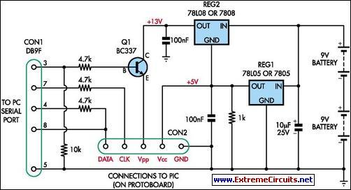
This simple programmer accepts any device supported by software. The circuit is partially based on the ISP header described in the SILICON CHIP "PIC Testbed" project and features an external programming voltage supply for laptops and other situations where...
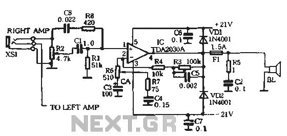
The circuit comprises two main components: the Lisheng power amplifier and the rectifier filter section. The stereo audio power amplifier circuit diagram, depicted in Figure 5-85, illustrates only one channel, with the other channel being identical. The audio signal...
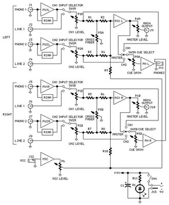
The mixer circuit features two line inputs and two microphone inputs, along with two line outputs. The microphone inputs are designed for low-impedance dynamic microphones with an impedance range of 200-1000 ohms. This simple mixer was specifically designed to...
Provision in the speed of a small engine DC motor speed control circuit using a small rheostat for control in the DC motor circuit diagram. The circuit for controlling the speed of a small DC motor typically incorporates a rheostat...
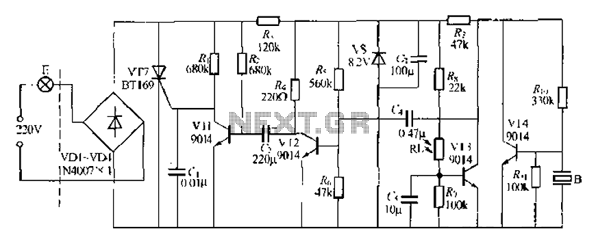
A modified piezoelectric ceramic acoustic-electric transducer is utilized to create a sound and light control system for a stairway walkway with a delay lighting switch. The circuit structure is relatively simple, consisting of diodes VD1 to VD4 and a...