
DC Motor speed control circuit

The circuit for controlling the speed of a small DC motor typically incorporates a rheostat as a variable resistor, allowing for manual adjustment of the motor's speed. The basic configuration includes a DC motor, a power supply, and a rheostat connected in series with the motor.
When the rheostat is adjusted, it alters the resistance in the circuit, which in turn modifies the voltage across the motor. As the resistance increases, the voltage supplied to the motor decreases, resulting in a reduction of the motor's speed. Conversely, reducing the resistance allows more voltage to reach the motor, increasing its speed.
In a typical schematic, the DC motor is represented by a circle with terminals labeled accordingly, while the rheostat is depicted as a resistor symbol with an adjustable slider. The power supply is often represented by a pair of parallel lines, indicating the positive and negative terminals.
It is important to consider the specifications of the rheostat to ensure it can handle the current required by the motor without overheating. Additionally, the power supply voltage should match the motor's rated voltage to prevent damage.
For applications requiring more precise speed control or efficiency, alternatives such as pulse width modulation (PWM) circuits can be implemented. However, for basic speed control needs, a simple rheostat in series with the motor provides an effective and straightforward solution.Provision in the speed of a small engine DC Motor speed control circuit of Service By a small rheostat control In DC motor Circuit diagram. 🔗 External reference
Related Circuits
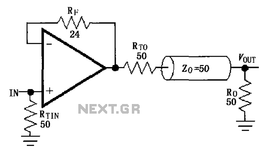
The MAX4450/4451 unity gain line is illustrated in the driving circuit. The MAX4450/4451 features internal compensation, a 24-ohm resistor in series within a feedback loop, along with capacitors and inductors that can reduce the Q value of the feedback...
This circuit can be utilized in various devices to extract residual energy from seemingly depleted batteries. It is possible to connect multiple dead batteries in order to maximize energy extraction. This circuit design, often referred to as a Joule Thief,...
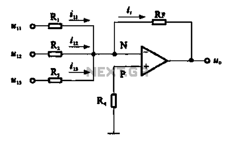
An adder circuit, specifically the inverting adder circuit, utilizes the inverting input of an operational amplifier to process signals. Voltage inputs are added through resistors connected to the inverting input terminal of the operational amplifier. The circuit configuration, as...
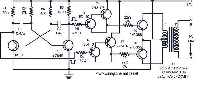
The following circuit is a cost-effective, fully transistorized inverter circuit suitable for driving medium loads in the range of 40 to 60 watts, operating with a 12V, 15 Ah battery or a larger power capacity. Transistors T1 and T2...
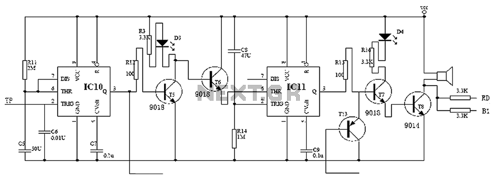
Child lock voltage comparator 555 monostable circuit, a counter, JK flip-flop, UPS power supply design digital logic circuit, electronic door control, and various additional circuitry to ensure the safety circuit can operate with a high safety factor. The circuit...
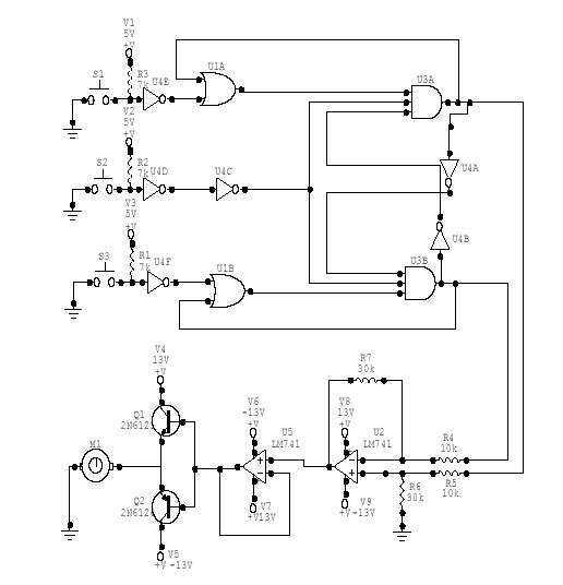
This DC Motor Controller circuit will control a 12V dc motor. The system will have three pushbuttons: a START button, a REVERSE button and a STOP button. Initially, the motor must not be running. When the START button is...