
3 phase sinewave generator

This circuit utilizes a Wien oscillator configuration, which is renowned for its ability to generate sine waves with high stability and low distortion. The operational amplifiers in the circuit serve as the core active components, providing the necessary gain and phase manipulation. The Wien oscillator consists of a feedback network made up of resistors and capacitors that determine the frequency of oscillation. The phase relationship between the output of the oscillator and the feedback junction is critical, as it dictates the stability of the oscillation.
In this modified version, the removal of preset potentiometers simplifies the design while still allowing for adequate control of output characteristics through fixed resistors. The choice of resistors in series allows for a more stable configuration, reducing variability introduced by mechanical components. The slight variations in output amplitude and phase due to the mechanical play in the potentiometer are acknowledged but deemed acceptable for the circuit's application, which does not require precision adjustments.
The operational amplifiers are configured in a way that ensures the output signals are coherent and maintain the desired phase relationships. The careful selection of resistor values is essential to achieving the desired frequency response and output characteristics. This design emphasizes reliability and ease of use, making it suitable for applications where minor variations in output are permissible. Overall, the circuit effectively demonstrates the principles of oscillation and phase control, providing a functional solution for generating stable sine wave outputs.I would have assumed that anyone interested in building one of these would have a reasonable understanding of electronics in general and the use of operational amplifiers in particular. This circuit relies on the fact that the phase difference between the output of a Wein oscillator and the junction of the CR in the series feedback is constan
t, regardless of the oscillation frequency. Phases are derived from adding appropriate magnitudes and signs of voltages obtained from these two. It is my version of a circuit I came across in commercially built equipment. The original had a few pre-set pots so one could adjust the amplitudes of and phase differences between the outputs. The pots have been eliminated by using two resistors in series in a couple of places. Due to a bit of lost motion between the shaft and rear section of the dual amplitude-setting pot, there is a very small variation in the amplitudes and phases of the outputs as the direction of rotation is changed.
This would have made a total nonsense of using the afore-mentioned pre-sets. It is of no consequence in the application for which it was built, but is a bit disappointing in a pot of this pedigree (Bourns). 🔗 External reference
Related Circuits

The device utilizes the USB boot HID keyboard protocol. When connected, it can detect changes in the keyboard LED states (caps lock, num lock, scroll lock), which the firmware uses to initiate new password generation (indicated by four LED...
The 4027 is a dual JK flip-flop that features independent clock, set, and reset inputs for each flip-flop, making it suitable for toggle, register, and control functions. It is capable of driving two low-power TTL loads and employs a...
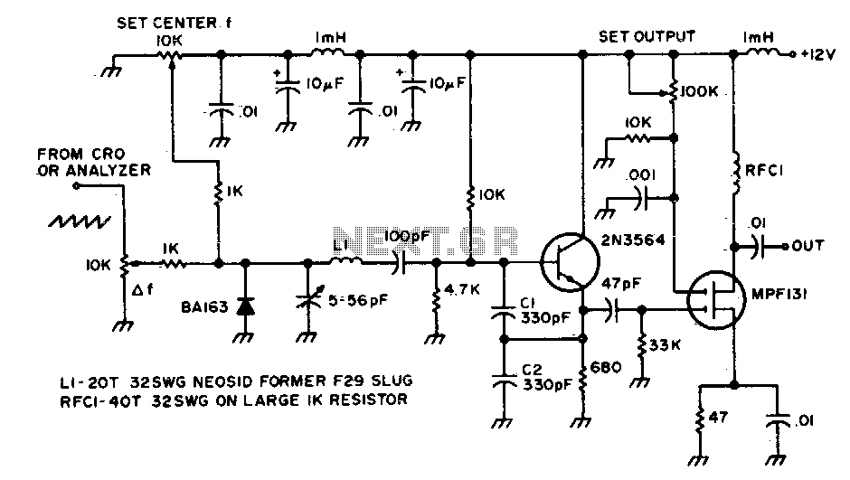
This circuit is utilized to observe the response of an intermediate frequency (IF) amplifier or a filter. It can be employed with an oscilloscope or, for a broader dynamic range, with a spectrum analyzer. The circuit designed for observing the...
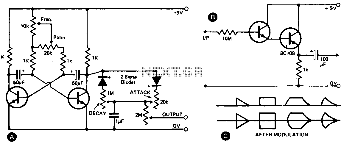
This waveshape generator functions as a slow-running oscillator with adjustable attack and decay times. It features a variable amplitude output, which is high impedance and can be controlled through a 2M potentiometer. Additionally, an add-on circuit is illustrated in...
The quadrature-grid signal is driven by a reference from the transmitter. This reference may consist of a sample of the unmodulated master oscillator, which provides a phase reference for the detector. The modulated waveform is applied to the limiter...

Generating sine waves with controlled frequencies over a wide range is challenging when using RC or LC sinusoidal oscillators. However, this can be effectively achieved using a wideband digital square wave oscillator, a counter, and a weighted summing network....