
Phase demodulation

In the described electronic circuit, the quadrature-grid signal plays a crucial role in phase detection and modulation processes. The reference signal, typically sourced from an unmodulated master oscillator, serves as a stable phase reference for the detection system. This configuration is essential in applications such as phase-locked loops and demodulation systems where precise phase relationships are critical.
The limiter grid receives the modulated waveform, which is subjected to gating action within the tube. This gating action is a result of the phase relationship between the incoming modulated signal and the reference signal. As the phase shifts, the gated-beam tube selectively allows current to pass, resulting in the output of current pulses. The characteristics of these pulses, particularly their width, are directly influenced by the phase difference between the carrier wave and the modulated waveform.
The output current pulses can be analyzed to extract information about the modulated signal, making this system particularly useful in communication systems where phase modulation is employed. The varying pulse widths can be visualized in a graphical representation, such as figure 3-20, which illustrates how the pulse width changes in response to different phase relationships. This behavior is critical for ensuring accurate signal interpretation and maintaining the integrity of the transmitted information.
In summary, the interaction between the quadrature-grid signal, the reference oscillator, and the modulated waveform is fundamental to the operation of the gated-beam tube, facilitating effective modulation and demodulation processes in electronic communication systems.The quadrature-grid signal is excited by a reference from the transmitter. This may be a sample of the unmodulated master oscillator providing a phase reference for the detector. The modulated waveform is applied to the limiter grid. Gating action in the tube will occur as the phase shifts between the input waveform and the reference. The combined output current from the gated-beam tube will be a series of current pulses. These pulses will vary in width as shown in figure 3-20. The width of these pulses will vary in accordance with the phase difference between the carrier and the modulated wave.
🔗 External reference
Related Circuits
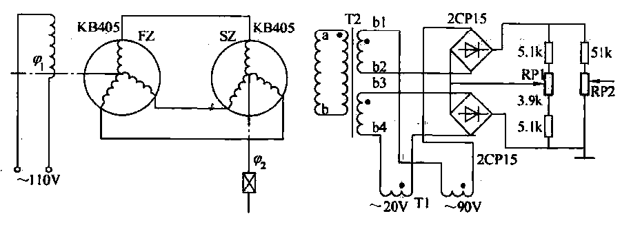
The transmitter (FZ) winding and receiver (SZ) correspond to the three-phase windings connected to a 110V AC voltage supply for transmission. The field winding, early start angle, and receiver output voltage at both ends of the stator windings reflect...
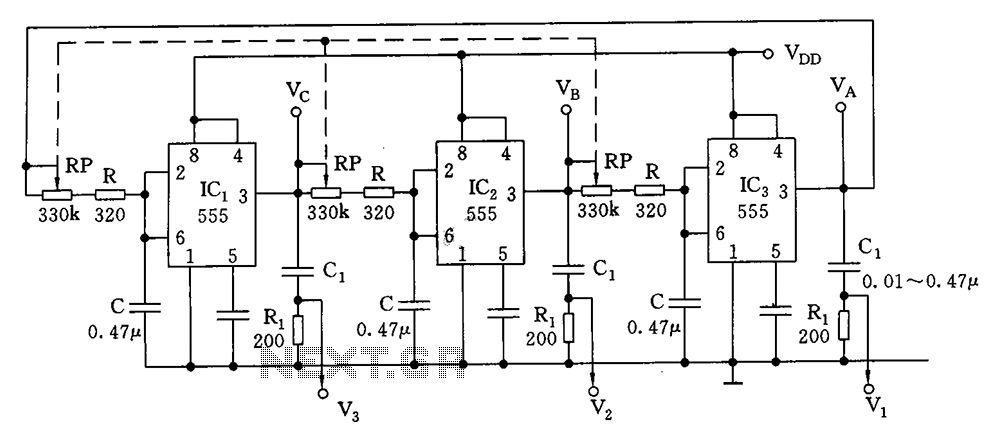
This circuit is a closed loop consisting of three identical Schmitt triggers connected in series. Each flip-flop has a delay time of td = (RP + R)C, where C represents the capacitance and RP is the resistance in the...
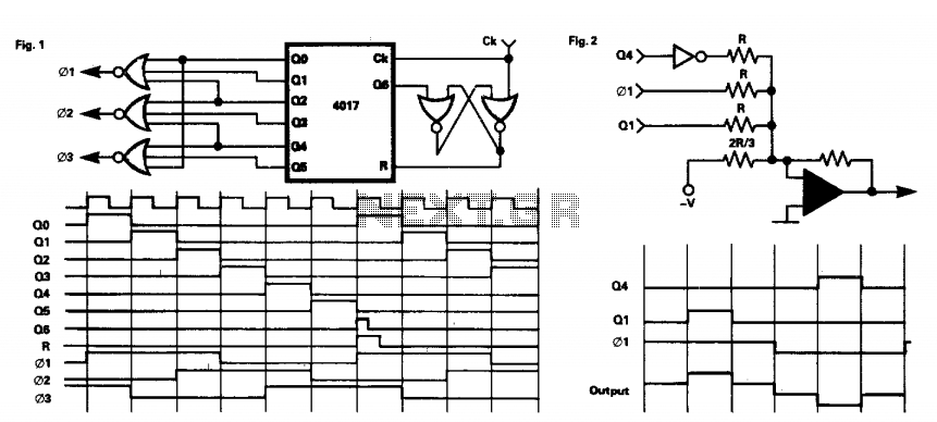
This circuit provides a three-phase square-wave output suitable for a variable speed motor drive. The operation is simple, as the 4017 counter is synchronously reset after six clock pulses. The outputs are combined to produce the necessary waveforms. It...
This is a schematic diagram of a video amplifier circuit with bi-phase output. The bi-phase output generates both positive-going and negative-going signals, enabling balanced signaling. The primary component of this circuit is the LM1201. In this configuration, the inverted...
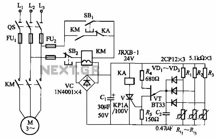
The thyristor control circuit includes a bridge circuit designed to regulate the temperature in the contactor coil KM, along with a secondary winding that functions as a power protection device. It comprises a thermistor (R:., Rt3) and a resistor...
The circuit serves as a foundational design, requiring experimentation for specific applications. In popular microwave bands, local oscillators (LOs) are typically generated using overtone crystal oscillators followed by multipliers. A table presents the standard LO frequencies for narrowband segments,...