
3000w inverter

The 3000W inverter circuit typically utilizes integrated circuits (ICs) for various control and operational functions. IC1 and IC2 may serve as key components in managing the inverter's switching operations, providing the necessary drive signals to the power MOSFETs or transistors that handle the high current output. Understanding their specific functions requires consulting the datasheets or application notes associated with the particular ICs used in the design, as they will detail the pin configurations, operational modes, and electrical characteristics.
Transformer construction is critical in inverter applications. The core size is determined based on the power rating and frequency of operation. A ferrite core is commonly used for high-frequency applications, while silicon steel might be utilized for lower frequencies. The wire gauge must accommodate the current without excessive heating, typically determined by the American Wire Gauge (AWG) standard. The number of turns for both primary and secondary windings is calculated based on the desired voltage transformation ratio and the core's magnetic characteristics.
For sourcing difficult-to-find components like the BD170 FET or the 8.2nF crystal, alternatives can often be identified by examining the specifications and finding comparable parts with similar electrical characteristics, such as voltage ratings, current handling, and switching speeds. It is advisable to consult with component suppliers or databases to identify suitable replacements.
The addition of a cooling fan is a practical enhancement to manage thermal performance, especially in high-power applications. The inclusion of LED indicators for low battery voltage can provide a visual alert for users, improving the usability of the inverter. Lastly, whether the circuit can charge a battery depends on the design's specific topology and components; typically, dedicated charging circuits or functions must be integrated to facilitate battery charging safely and effectively.The inverter is nice, thanks for the circuit. Please sir can you send the full function of IC1 and IC2 in this 3000W inverter circuit, to my email: sundawax@yahoo. com First of all i would like to greet you a pleasant day. Sir i am happy when found your schematic diagram of your inverter and i want to build it, and i write this comment not only to
give thanks to you sir but also i need your help specially in building the transformer. Sir can i ask you on how to build it, in core what size should i use and what is the size of wire and how many turns in primary and the secondary winding and also the L1. Sir once again i am very thankful to you and i hope can help me at your convenient time thank you sir.
and you can send me a message sir in jamor71@yahoo. com thanks I AM A ENGINEER AND IM VERY HAPPY TO FIND YOUR SITE I WANT TO DESIGN THE CIRCUIT BUT IN MY COUNTRY IT VERY DIFFICULT TO FIND BD170 FET AND ALSO 8. 2NF 3. 2768MHZ CRYSTAL PLEASE CAN YOU GIVE ME ANY OPTION TO GET OR CAN I CHANGE THESE COMPONENT WHICH I JUST MENTION FOR ME THANX YOU Hello sir nice job, but i have a lot of questions to ask sir, which IC is go to be in IC1f, IC2F, IC3F and P1.
i will be very greatful sir. thanks and i will like to add cooling fan to it and led light for battery low and i want to know if this diagram can charge the battery. thanks 🔗 External reference
Related Circuits
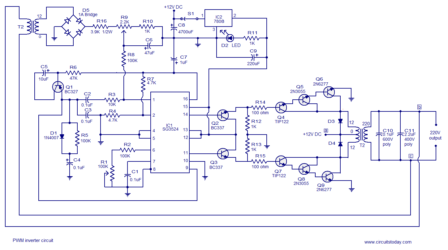
A simple PWM inverter circuit utilizes the SG3524 integrated circuit. This PWM inverter is designed for a 12V input, providing a 220V output with a maximum output power of 250 watts. The output power can be extended further. The described...
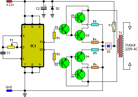
A 100 Watt inverter circuit utilizing a minimal number of components. It is challenging to construct a reliable inverter with even fewer components. This design employs the CD 4047 integrated circuit from Texas Instruments to generate 100 Hz pulses,...
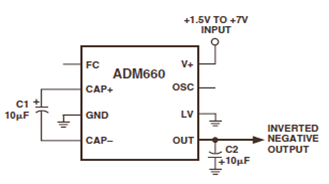
The ADM660 is a charge-pump voltage converter that can either invert the input supply voltage or double it. The schematic below depicts the ADM660 Voltage Inverter Circuit Configuration Diagram. This inverting schematic is ideal for generating a negative rail...
A 12V to 20000V inverter circuit diagram (stun gun) is presented. This circuit generates a very high voltage and must be used with caution to prevent electric shock. The transformer can produce over 1000V and amplify the voltage by...
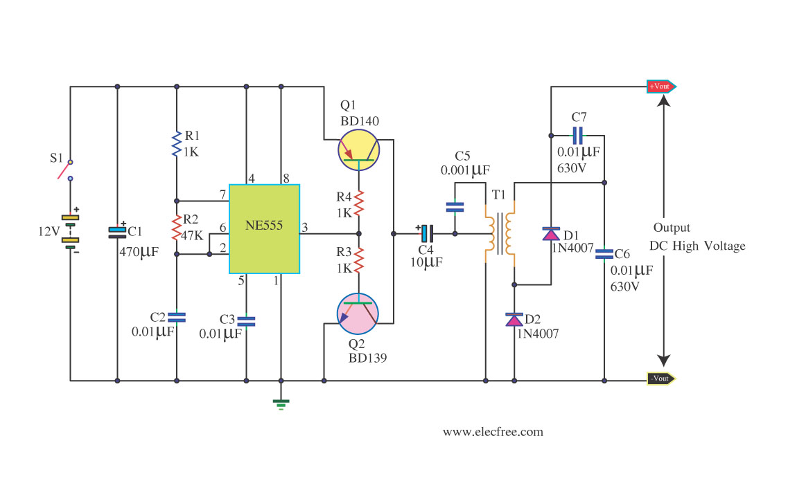
This circuit is a DC to DC inverter that can convert a 12V DC battery voltage to a high voltage of 300V DC. This circuit operates with low current. This DC to DC inverter circuit is designed to efficiently step...
This circuit is designed to convert 12V DC into 220V AC. It utilizes a 4047 integrated circuit to generate a 50Hz square wave, which is then amplified for current and voltage using a step-up transformer. The fundamental relationship between...