
30KV Power supply / Generator

The high voltage generator circuit described is a compact and effective design aimed at producing high voltage outputs, specifically up to 50 kV, although the effective output may be limited by the breakdown voltage of the coil used in the circuit. The primary components of this generator include T1, a small transformer, and T2, a car ignition coil, which is critical for generating the high voltage.
T1 serves as a step-up transformer, featuring a laminated iron core with a square cross-section measuring 7 mm by 7 mm and a length of 57 mm. The winding configuration consists of 75 turns on the collector side, which is responsible for the primary winding, and 25 turns on the base side, acting as the feedback winding. The use of 1 mm enamelled wire for these windings is essential to ensure sufficient insulation and current carrying capacity. The circuit's design is flexible, allowing for variations in transformer types, including ferrite transformers, which can also be employed to achieve similar functionality.
A notable aspect of this design is the inclusion of a 0.5 µF capacitor sourced from automotive applications, which is recommended for its reliability and performance characteristics. This capacitor plays a crucial role in the energy storage and discharge process, contributing to the oscillation and voltage generation within the circuit.
In the event that the circuit does not exhibit oscillation, one of the transformer windings may need to be inverted to rectify the issue. This adjustment can help initiate the oscillation required for high voltage generation. The transistor utilized in the circuit remains relatively cool during operation and does not necessitate a heatsink when mounted in a metal enclosure. However, if a non-metal case is used, a small heatsink rated at 5ºC/W can be employed to maintain optimal operating temperatures.
The operating frequency of the circuit is approximately 1.2 kHz, which is a suitable range for the effective operation of the ignition coil and transformer combination. This frequency is critical for achieving the desired high voltage output while ensuring the components operate within their safe limits. Overall, this high voltage generator design provides a straightforward approach to generating high voltages for various applications, with particular attention to component selection and circuit configuration to enhance reliability and performance.Easy to build, this high voltage generator is capable of generating up to 50KV but the breakdown voltage of the coil limits the voltage to a value somewhat lower. T2 is the ignition coil of a car and also the 0.5µF capacitor comes from the same place: actually I suggest using only this type of capacitor.
T1 is a small transformer with a laminated iron rod, with a square section of 7x7mm, 57mm long with 75 turns on the collector side and 25 turns on the base side made with a 1mm enamelled wire. Its implementation is not critical and I expect that the circuit will work with a wide variety of transformers including ferrite ones.
Try to invert one of the windings if the circuit does not oscillate. The transistor will stay quite cool and does not require a radiator if it is assembled on a metal case; otherwise a small 5ºC/W radiator will suffice. Frequency of operation is around 1.2KHz. 🔗 External reference
Related Circuits
A Variable DC Power Supply is one of the most useful tools on the electronics hobbyist's workbench. This circuit is not an absolute novelty, but it's simple, reliable, rugged, and short-proof, featuring variable voltage up to 24V and variable...
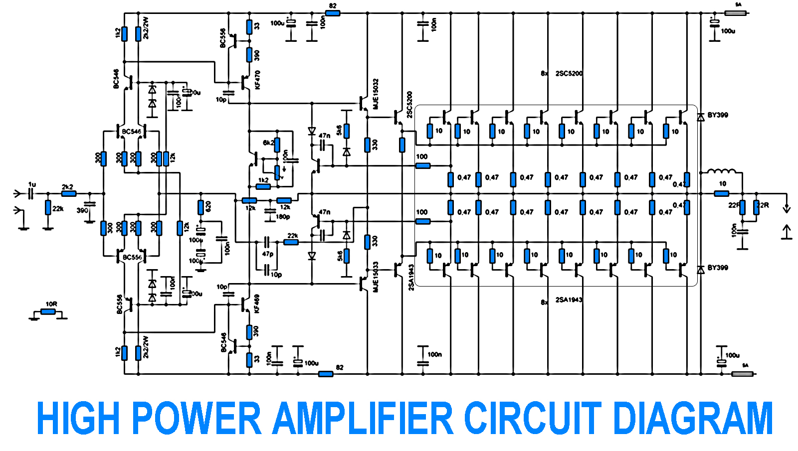
700W Amplifier. Adjusting the amplifier power to 700W appears straightforward, yet it is essential to consider the adjustment of the driving transistors and the frequency offset engagement. It is necessary to modify the current protection circuit that safeguards the...

This document presents a basic electronics project focused on creating a regulated power supply. A regulated power supply is essential for various electronic circuits, as it provides a constant voltage necessary for their operation. Understanding how to construct a...
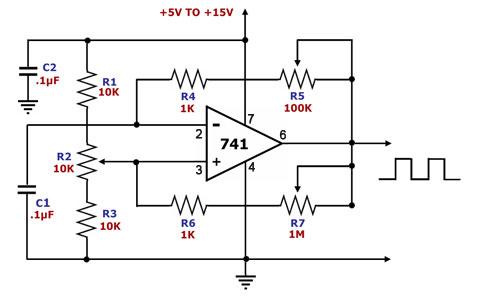
This is a square wave generator circuit. The primary component of this circuit is the 741, a general-purpose operational amplifier. The circuit operates with a single power supply voltage (Vs) that can vary between +5V and +15V. The square...
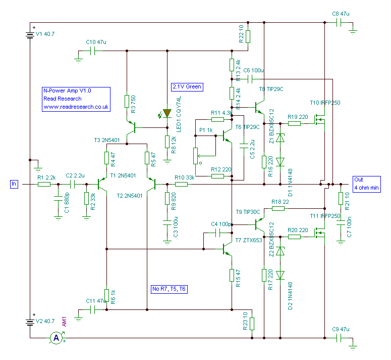
The amplifier has been designed as an ideal upgrade for builders looking to advance from Gainclones. This amplifier delivers power where Gainclones may struggle, while still producing a pleasant sound. The implementation of n-channel MOSFETs in the output stage...
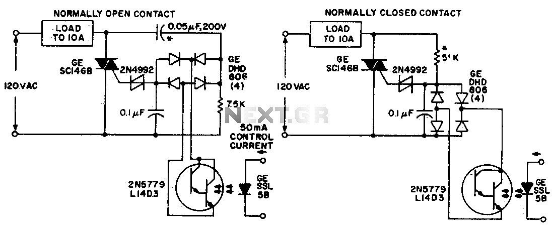
Both circuits utilize the GE SC146B, a 200 V, 10 A Triac for load current contacts. These triacs are activated by standard SBS (2N4992) trigger circuits, which are managed by a photo-Darlington configuration, functioning through the DA806 bridge as...