
30V Volt Meter with PIC16F676

The circuit operates by first dividing the input voltage using a resistor network, which scales the voltage to a level suitable for the PIC16F676's ADC. The microcontroller converts the analog voltage signal into a digital value through its 10-bit ADC, providing a maximum resolution of 1024 discrete levels for the input voltage range. This digital value is then processed to determine the corresponding voltage reading.
The three common anode seven-segment displays are wired in a multiplexed arrangement to minimize the number of I/O pins required from the microcontroller. By switching between the displays at a high frequency, the human eye perceives the outputs as a continuous display. Each segment of the display is controlled by the microcontroller, which turns on the appropriate segments to represent the digits of the measured voltage. The time each display is activated is carefully calculated to ensure that all displays are visible and legible without flickering.
The design also includes necessary decoupling capacitors near the power supply pins of the microcontroller to ensure stable operation. The circuit may also incorporate additional components such as a zener diode for overvoltage protection, ensuring that the input voltage does not exceed the maximum rating of the ADC. This setup allows for accurate voltage measurements while protecting the microcontroller from potential damage due to excessive voltage levels. Overall, this voltmeter circuit provides a reliable and efficient means of measuring DC voltages up to 30V in various applications.This is a simple 30V volt meter using PIC16F676 micro controller with 10-bit ADC (analog to digital converter) and three 7 segment LED displays. You can use this circuit to measure up to 30V DC. The possible applications are on bench power supply or as a digital panel meter in various systems. PIC16F676 is the heart and brain of this circuit. The internal adc of the mcu with a resistor network voltage divider is used to measure the input voltage.
Then 3 digits of comm anode 7 segment display is used to display final converted voltage. As you can see in the schematic the displays are multiplexed with each other. It means we switch on one display and put the corresponding digit on this while other two displays are off this cycle goes for each of the displays 🔗 External reference
Related Circuits
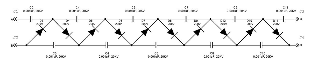
The Cockcroft-Walton multiplier employs a series of diodes and capacitors arranged in a cascade to generate a high-voltage DC potential from an AC input. This circuit topology utilizes diodes to charge capacitors in parallel and discharge them in series....
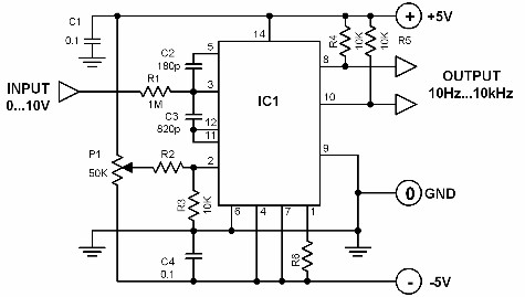
A voltage-to-frequency converter with a control range of 1:1000 can be constructed using the IC TSC9402. The specified component values in the circuit yield a conversion factor of 1 kHz per 1 V. Input voltages ranging from 10 mV...
Voltage variations and power cuts adversely affect various equipment such as TVs, VCRs, music systems, and refrigerators. This simple circuit will protect the costly equipment from high as well as low voltages and the voltage surges (when power resumes)....
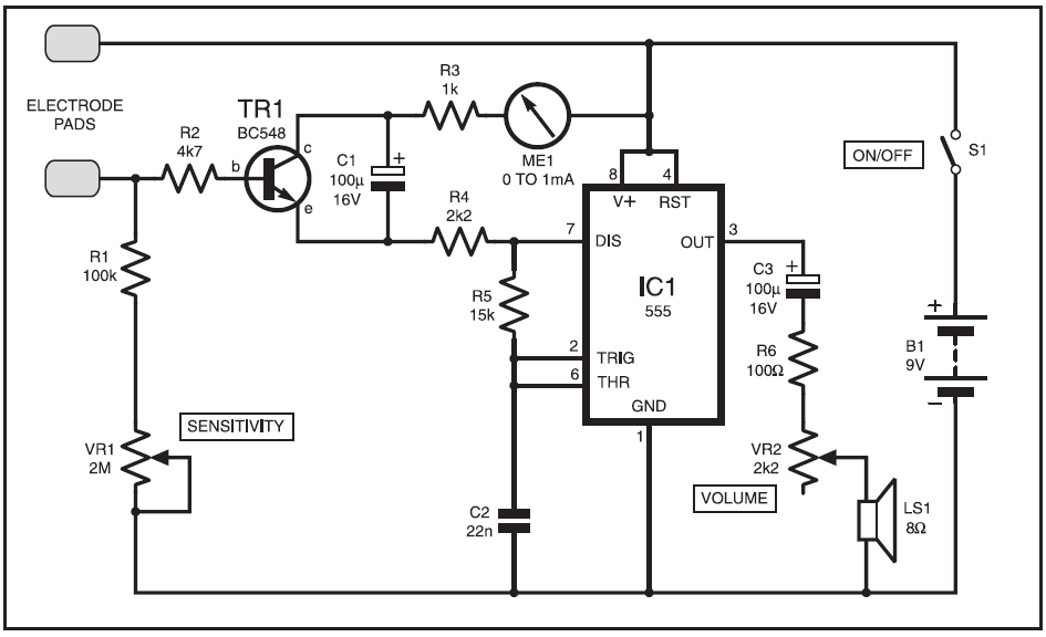
This instrument is designed to help relieve nervous tension for individuals returning home from work with lingering stress. Known as the Galvanic Skin Response Monitor, it operates based on changes in skin resistance that correlate with emotional states. Increased...
Before designing an adjustable voltage regulator into a circuit or performing a redesign, it is essential to calculate the values for two resistors. While this calculation is straightforward, locating the appropriate resistors may present challenges. Fortunately, a technique exists...
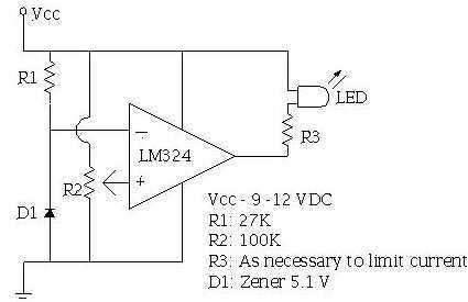
An ECU must have a way to monitor battery voltage. Here is a simple op-amp based circuit which will illuminate the LED when the battery voltage drops to a certain level. The turn-on point is set with R2. You...