
High-Low Voltage Cutout with delay

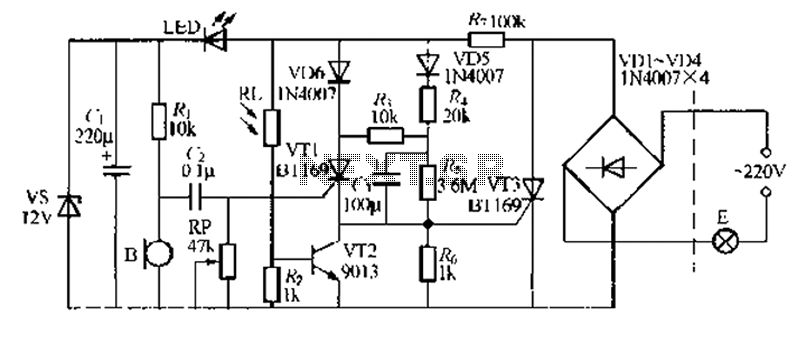
The circuit described functions as a protective device for sensitive electronic equipment, safeguarding against voltage fluctuations and power interruptions. The primary components include zener diodes D4 and D5, transistors T1 and T2, relay RL1, and the 555 timer IC configured in monostable mode.
In normal operating conditions, the circuit maintains a stable output, with zener diode D5 ensuring that the voltage remains above the threshold to keep transistor T2 conducting. This allows relay RL1 to remain energized, providing power to connected devices while the green LED indicates normal operation. Under high voltage conditions, the zener diode D4 activates, turning on transistor T1 and cutting off the current to transistor T2, which de-energizes the relay and disconnects the load to prevent damage.
In cases of low voltage, both transistors T1 and T2 are turned off, resulting in the relay being de-energized and protecting the load. The 555 timer IC plays a crucial role in generating a delay, allowing for a brief pulse to trigger the music IC UM66 when power is restored. This feature not only provides an audible indication of power restoration but also serves as a reminder that the protective measures are in place.
The circuit's design includes adjustable presets VR1 and VR2 for fine-tuning the voltage thresholds, allowing for flexibility in operation based on the specific requirements of the equipment being protected. The use of an auto-transformer for calibration ensures that the circuit can be accurately adjusted to respond to varying voltage levels, enhancing its effectiveness in real-world applications. The volume control VR3 allows for user preference in the output sound level, further personalizing the user experience.
Overall, this circuit serves as a comprehensive solution for protecting electronic devices from damaging voltage conditions while providing a user-friendly interface for adjustments and notifications.Voltage variations and power cuts adversely affect various equip- ment such as TVs, VCRs, music systems and refrigerators. This simple circuit will protect the costly equipment from high as well as low voltages and the voltage surges (when power resumes).
It also gives a melodious tune when mains power resumes. When mains voltage is normal, the DC voltage at the cathode of zener diode D4 is less then 5.6V. As a result transistor T1 is in off state. The DC voltage at the cathode of zener diode D5 is greater than 5.6V and as a result transistor T2 is in on state. Consequently, relay RL1 gets energised, which is indicated by lighting up of green LED. Under high mains voltage condition, transistor T1 switches to on state because the voltage at cathode of zener diode D4 becomes greater than 5.6V. Consequently, transistor T2 switches to off state, making the relay to de-energise Under low mains voltage condition, transistor T1 switches to off state and as a result transistor T2 also switches to off state, making the relay to de-energise.
Timer IC 555 in the circuit is configured to operate in a monostable mode. The pulse width is about 10 seconds with the timing component values used in the circuit. When the power resumes after a break, pin 2 of IC 555 goes low briefly and this triggers it. Its output makes music IC UM66 to operate through transistor T3. Simultaneously, transistor T1 also gets forward biased as the monostable IC1 output is connected to its base via diode D8 and resistor R7. As a result, transistor T1 conducts and biases transistor T2 to cut off. Thus relay RL1 remains de-energised for the duration of mono pulse and the load is protected against the voltage surges.
To adjust presets VR1 and VR2, you may use a manually variable auto-transformer. Set the output of auto-transformer to 270V AC and connect it to the primary of transformer X1. Adjust preset VR1 such that relay RL1 just de-energises. Next set the output of auto-transformer to 170V AC. Now adjust preset VR2 such that relay RL1 again de-energises. Volume control VR3 may be adjusted for the desired output volume of the tune generated by IC UM66. 🔗 External reference
Related Circuits
A relatively simple circuit for controlling a stair walkway light with a delay feature. The circuit has a drawback in that the voice activation is somewhat less sensitive, making it sometimes difficult to trigger with general conversation. However, it...
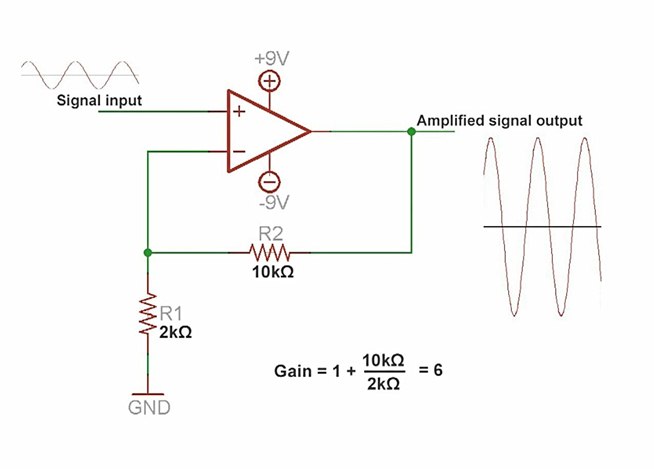
An amplifier is a device that increases the voltage in a circuit. The simplest type is an operational amplifier, and this video will demonstrate how these devices function and how to implement them in electronic applications. As an example,...
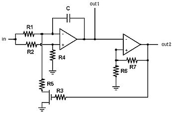
A voltage-controlled oscillator (VCO) is an electronic oscillator designed to control its oscillation frequency through a voltage input. The oscillation frequency is varied by the applied DC voltage, and modulating signals can also be introduced to the VCO for...
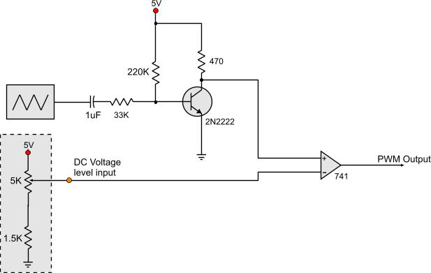
Circuits that generate PWM pulses typically translate a resistor value into a change in duty cycle. While this method is convenient, there are instances where a voltage-controlled PWM generator is required. Although microcontrollers can produce a variety of PWM...
Opening a car's door is a straightforward activity that typically requires no special skills. It is a routine task that is generally trouble-free; however, issues can occasionally arise. The process of opening a car door involves several mechanical and electronic...
Power line fluctuations and cut-offs can damage electrical appliances connected to the line, particularly domestic appliances such as refrigerators and air conditioners. When a refrigerator operates at low voltage, excessive current flows through the motor, leading to overheating and...