
3D Laser Scanner

The described scanning system integrates several components to facilitate the capture of high-quality 3D scans of objects, particularly those with organic forms. The use of a red laser line, coupled with a precise sweeping mechanism powered by a down-geared NXT motor, allows for controlled and accurate scans. The calibration process, aided by reference planes marked with black dots, enhances the software's ability to interpret the data collected by the webcam, ensuring that the resulting scans are both detailed and reliable.
The choice of a Logitech Pro 9000 webcam is significant due to its superior image quality, which is essential for capturing the intricate details of the scanned objects. However, the absence of a mounting hole necessitates modifications to the hardware setup, highlighting the need for adaptability in engineering design. The interface board, equipped with a transistor and diode, is a critical component that ensures the laser operates within safe voltage limits, thereby preventing damage and ensuring consistent performance.
The control interface design, mirroring the functionality of existing LEGO light sensors, simplifies user interaction by allowing straightforward programming of the NXT ports. This design choice not only leverages existing technology but also reduces the learning curve for users familiar with LEGO robotics.
The scanning process itself is methodical, with the software interface guiding users through speed selection and scan initiation. The ability to rotate the object in fixed increments allows for comprehensive coverage of the subject, although the limitation of tilting poses a challenge that may require further innovation in the hardware design.
In summary, the described system exemplifies a thoughtful integration of hardware and software components to achieve high-quality 3D scanning. By addressing potential challenges and optimizing the design for specific scanning tasks, this setup demonstrates the versatility and capability of modern electronic engineering in the field of 3D modeling.The red laser line slowly sweeps the object (here a Fabuland lamb head). Behind the scanned object, two planes with a 90 ° angle provide reference to the scanning software. They are also marked with regularly spaced black dots that serve during the calibration process that inform scanning software of webcam characteristics, field of view, optics distortion. The laser sweeping mechanism. The NXT motor is down-geared by 1:2880, providing a really slow motion. The two white rubber bands maintain tension on the gears to avoid gear lash. The NXC code allows to set the scan speed through motor speed variation, and to move the laser at maximum speed during scan setup. Below the sweeping mechanism there is a Logitech Pro 9000 webcam. This high quality webcam provides very good images, thus detailed scans (though I made my first tries with a much lower cost Trust webcam).
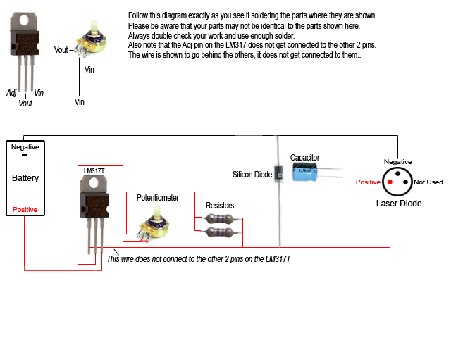
The drawback of this webcam is that it doesn` have a screw mounting hole, here is how I added one. The laser itself is powered from the NXT through a sensor port. The small interface board in the middle of the cable contains a transistor to switch the laser on/off (the same way as the LED of NXT light sensor) and a series diode to lower voltage. Schematics of the control interface. D2 is a small silicon diode (1N4148) whose purpose is to lower voltage on the laser, since lightly loaded NXT IO supply can exceed the 4.
5V maximum rating of the laser used. Q1 is a small NPN transistor (BC548, 2N3904. ) used to control laser with DIGI0 NXT I/O pin. This is the same circuitry as the one used in the LEGO light sensor to control the red LED, so the laser can be controlled the same way. Program the port as a reflected light sensor to light up the laser, and as an ambient light sensor to put it off.
Top view of the scan bench. The second NXT motor is able to rotate the object to acquire different angles of view. It would be necessary to be able to tilt the object to see above and under. Unfortunately I have not yet found a way to do this without blocking camera sight on the panels behind. So I replace straight axle mount with assemblies containing angle connectors. The program is very simple, you first choose scan speed, then pressing orange button you go to the main scanning screen.
The laser lights up. Pressing the right or left NXT key allow you to start scan in up or down direction. Pressing left or right for a more than one second toggle to high speed mode to pre-position laser line before actual scan. Pressing orange button again, you go to the object rotation mode that allows to turn the object by 45 ° increments.
Orange again comes back to scan mode. Choose the part to model. Geometrical shapes are not interesting to build through 3D scan, the models created this way contain a lot of triangles so this process is best for organic shapes, as you can see in gallery above. The laser line on the object must be clearly visible by the camera. The part must be lightly colored and without patterns. Otherwise you need to "paint" it in white color. I generally use a chalk spray paint, but white tempera with a drop of detergent works too. You`ll then need to carefully clean the object after scanning with a fine brush! install the object on the scanner and start scanning. You will need to perform scans from 🔗 External reference
Related Circuits
Construct a custom burning laser. This guide outlines a proper method for building a burning laser, ensuring a long lifespan for the device. There are multiple advantages to this approach over simply connecting the laser diode to batteries, which...
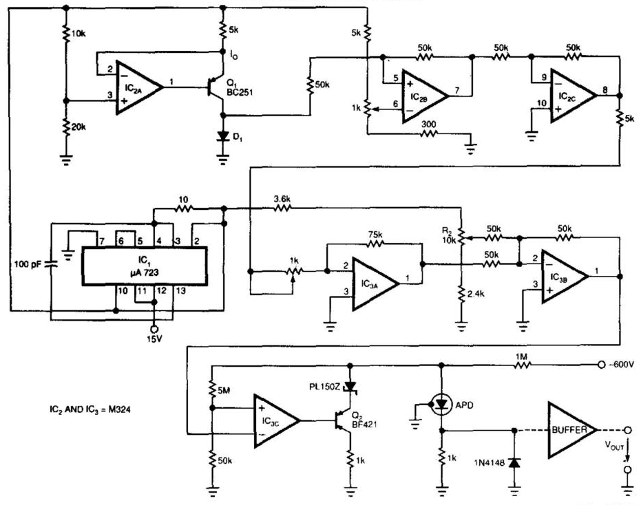
Laser-receiver circuits must bias their avalanche photodiodes (APD) to achieve optimal gain. Unfortunately, an APD's gain depends on the operating temperature. The circuit controls the operating voltage of an APD over a large temperature range to maintain the gain...
The development of the entire system necessitated a thorough identification of all processes related to the laser controller. The initial diagram outlines the primary physical components utilized in the CNC laser system. The setup includes a power supply, a...
The SSY-1 is a compact pulsed Nd:YAG laser that was initially utilized as part of the laser rangefinder in the M1 Abrams tank. The laser head and PFN-1 pulse forming network, which includes a flashlamp capacitor, inductor, and diode,...
Many individuals who invested in Prologic decoders are now considering Dolby Digital technology. New formats such as DSS, DVD-Video, and High Definition Television incorporate this technology; however, the older laserdisc format also deserves attention, as over 600 laserdiscs feature...
This circuit is designed around a 555 timer and utilizes very few components. Its simplicity allows even novices to construct and use it as a control device. A laser pointer, widely available in the market, can be employed to...