
Laser Activated Switch

This circuit utilizes the popular 555 timer IC, which is known for its versatility and ease of use. In this particular application, the 555 timer is configured in bistable mode, allowing it to switch between two stable states based on input signals from the laser pointers. The circuit comprises two light-dependent resistors (LDRs), which serve as sensors to detect the laser beam. When the laser beam is directed onto LDR1, the resistance of LDR1 decreases, triggering the timer to activate the relay, which in turn powers the connected device. Conversely, when the laser beam is aimed at LDR2, the resistance of LDR2 decreases, causing the timer to deactivate the relay and turn off the device.
The operational range of 500 meters suggests that the circuit is suitable for various applications where remote control is desired, such as in home automation or remote device management. However, the requirement for low-light conditions is a critical design consideration, as the LDRs rely on ambient light levels to function correctly. In bright environments, the effectiveness of the LDRs may be compromised, leading to unreliable operation.
The circuit's simplicity is a significant advantage, making it accessible to hobbyists and individuals with basic electronics knowledge. The low cost of the components, with the circuit totaling under Rs 25, makes it an economical solution for remote control applications. Overall, this circuit exemplifies an effective and straightforward approach to utilizing a laser pointer for remote device control, with practical applications in everyday scenarios.This circuit is built around a 555 timer using very few components. Since the circuit is very simple, even a novice can easily build it and use it as a controlling device. A laser pointer, now easily available in the market, can be used to operate this device. This circuit has been tested in operational conditions from a distance of 500 metres and was found to work satisfactorily, though it can be controlled from still longer distances. Aiming the laser beam exactly on to the LDR is a practical problem. The circuit is very useful in switching on/off a fan at night without getting off the bed. It can also be used for controlling a variety of other devices like radio or music system. The limitation is that the circuit is operational only in dark or dull-lit environments. By focusing the laser beam on LDR1 the connected gadget can be activated through the relay, whereas by focusing laser beam on LDR2 we can switch off the gadget. The timer is configured to operate in bistable mode. The laser pointers are available for less than Rs 30 in the market. The cost of the actual circuit is less than Rs 25. 🔗 External reference
Related Circuits
Nowadays, many intercom units are equipped with video cameras, allowing users to see as well as hear who is at the door. Unfortunately, the camera lens is... Intercom systems with integrated video capabilities enhance security and convenience by enabling visual...
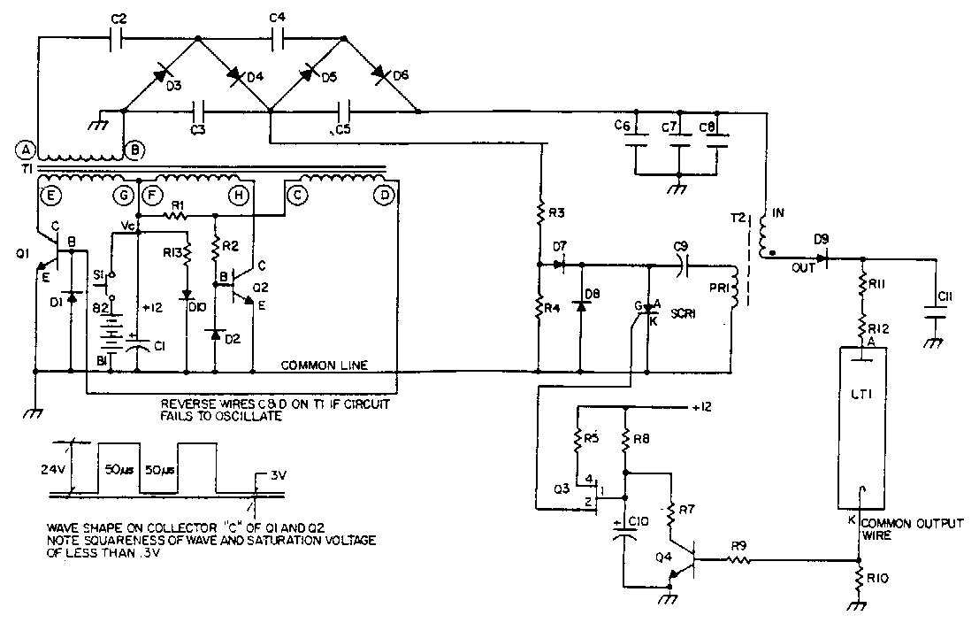
Q1 and Q2 control the primary windings of transformer T1 using a square wave signal, the frequency of which is determined by the magnetic properties of the transformer. Diodes D1 and D2 serve as base return paths for the...

This circuit is designed for differential analog circuit switches. The FM1208 monolithic dual differential multiplexer is utilized in applications where the RDS (ON) must be closely matched. The RDS (ON) for the monolithic dual multiplexer operates with a precision...
This simple circuit, as shown in the schematic diagram, activates a switch using sound. It can be utilized for various applications, such as an automatic sound-controlled disco light or a car's LED light show. The transistor Q1 amplifies the...
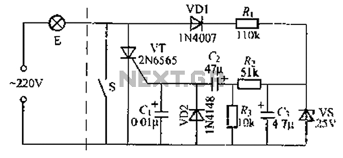
A delay circuit using an improved quenching lamp pull switch is described, focusing on its performance and the delay function in lighting control. The circuit exhibits a high degree of stability and reliability. When switch S is closed, the...
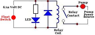
A float switch is a device commonly used to measure the depth or level of liquid in a container. When the liquid rises to the level of the float switch, the float rises, transitioning from a vertical to a...