
3khz Low Pass Filter and Audio Amplifier

The circuit design incorporates a switched capacitor filter IC, which is a pivotal component in signal processing applications. The primary function of this filter is to attenuate frequencies above 3 kHz, allowing only the desired voice audio frequencies to pass through. This is particularly useful in telecommunications and audio applications where clarity of voice signals is paramount.
The switched capacitor filter operates by periodically switching capacitors in and out of the circuit, effectively sampling the input signal at a specific rate. This method allows the filter to achieve a high level of precision and stability without the need for large passive components. The filter's cutoff frequency is determined by external resistors and capacitors, which can be adjusted to tailor the filtering characteristics according to the specific application requirements.
In practical applications, the circuit may include additional components such as operational amplifiers to buffer the output signal and ensure that the load does not affect the filter performance. Power supply decoupling capacitors might also be included to minimize noise and improve the stability of the filter operation.
The output of the circuit can be connected to further processing stages, such as an analog-to-digital converter (ADC), where the filtered audio signal can be digitized for further processing, storage, or transmission. Overall, this circuit provides an effective solution for filtering unwanted high-frequency noise from voice audio signals, enhancing the quality and intelligibility of the audio output.This circuit uses a switched capacitor filter IC from National Semiconductor to filter signals with frequencies higher than the 3KHz needed for voice audi.. 🔗 External reference
Related Circuits
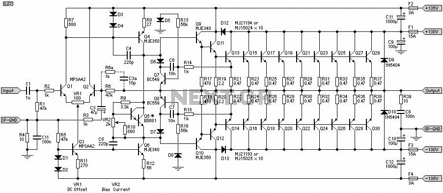
This 1500W Power Amplifier Circuit Diagram contains two images of the circuit. For more complete information, refer to the main post titled "1500 Watt Power Amplifier." It includes a list of component parts for the 1500W Power Amplifier Circuit...
Circuit description of a VHF pre-amplifier using a grounded base configuration. The VHF pre-amplifier circuit utilizing a grounded base configuration is designed to amplify very high-frequency signals while maintaining a low noise figure and high input impedance. This configuration is...
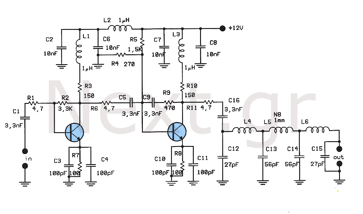
This amplifier is designed to amplify low-level signals from oscillators in the FM band. It lacks frequency regulators with variable capacitors and coils, providing a wide range and moderate power suitable for driving multiple linear amplifiers. The construction utilizes...
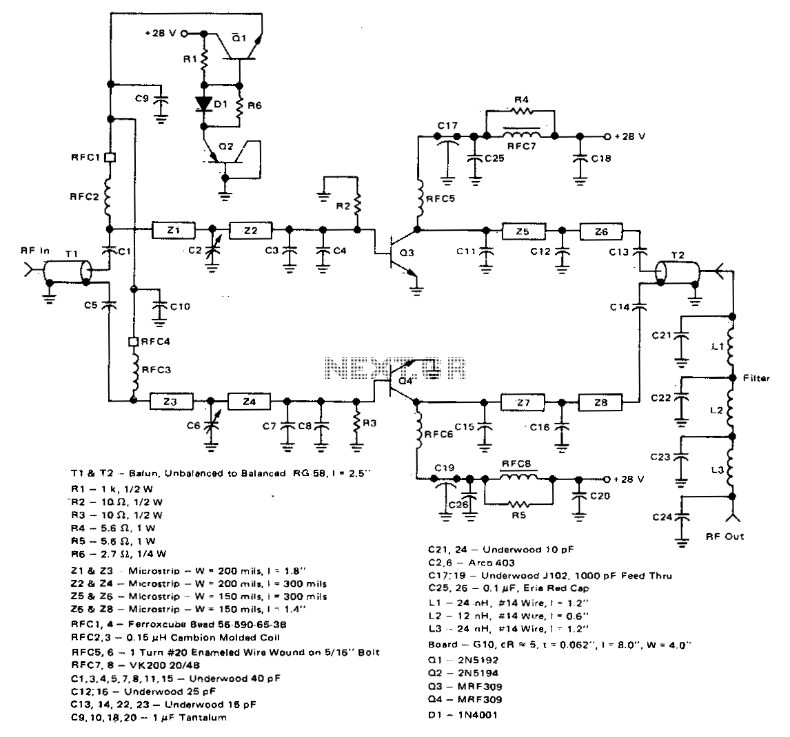
This 100-watt linear amplifier can be built using two MRF309 transistors in a push-pull configuration, requiring only 16 watts of drive power within the frequency range of 420 to 450 MHz. It operates from a 28-volt supply and achieves...
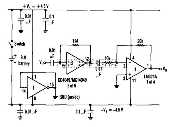
When an inverter is biased with a resistor from its input to output in the range of 100 kΩ to 10 kΩ and is capacitor coupled, it exhibits amplifier characteristics. Furthermore, when a split power-supply bus is needed and...
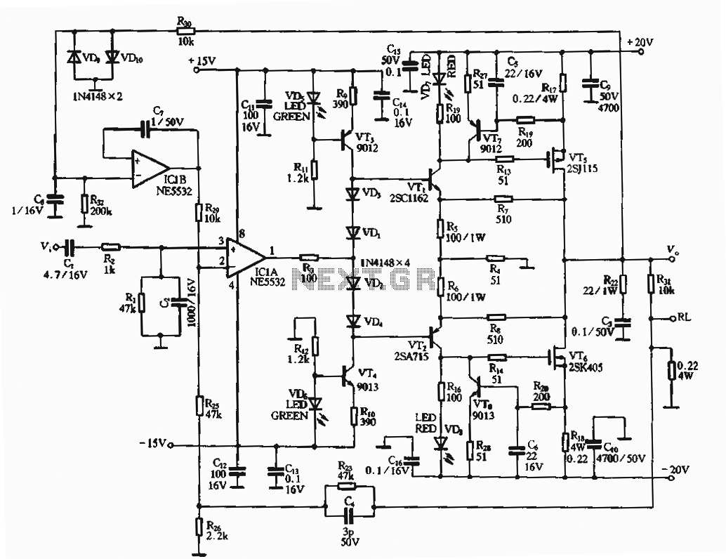
The circuit utilizes an FET amplifier configuration for output, incorporating an NE5532 operational amplifier powered by a 15V supply. The output stage features a FET that amplifies the voltage after passing through several stages. The bias circuit for the...