
VHF Pre-amplifier

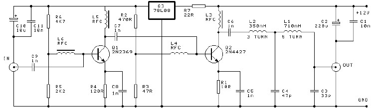
The VHF pre-amplifier circuit utilizing a grounded base configuration is designed to amplify very high-frequency signals while maintaining a low noise figure and high input impedance. This configuration is particularly advantageous for applications in radio frequency (RF) communications, where signal integrity is crucial.
In a grounded base amplifier, the base terminal of the transistor is connected to the ground. This configuration allows for a high-frequency response due to the reduced capacitance effects at the input. The input signal is applied to the emitter, while the collector is connected to the power supply through a load resistor. This arrangement facilitates the amplification of the input signal with minimal distortion.
The circuit typically employs a high-frequency transistor, such as a bipolar junction transistor (BJT) or a field-effect transistor (FET), chosen for its ability to operate effectively at VHF frequencies. The biasing of the transistor is critical to ensure proper operation; therefore, resistors are used to set the operating point, allowing the transistor to remain in the active region during signal amplification.
The output is taken from the collector, and it is often coupled to the next stage of amplification or processing through a coupling capacitor. This capacitor blocks any DC component while allowing the amplified AC signal to pass. Additional components, such as bypass capacitors, may be included to stabilize the power supply and filter out noise, ensuring that the amplified signal remains clean and usable.
Overall, the grounded base configuration in a VHF pre-amplifier circuit is effective for enhancing signal strength while minimizing noise, making it suitable for various RF applications, including television and radio broadcasting, as well as communication systems.Circuit description of a VHF Pre-amplifier using a grounded base configuration 🔗 External reference
Related Circuits
This document presents a schematic diagram of an electret microphone pre-amplifier utilizing the LMV721 operational amplifier. The LMV721 is chosen for its low noise and low power characteristics. The electret microphone pre-amplifier circuit is designed to amplify the weak audio...
Many designers assert that NFB loop controlled amplifiers are inferior because they degrade the sound. However, it's worth considering what these individuals believe they are actually listening to. The reality is that most vinyl waveforms and CD pits, as part...

Below 10 MHz, the development of engineering models is relatively straightforward and not significantly influenced by printed circuit board layout. In the VHF range, parasitic circuit elements and unwanted coupling can severely impact efforts to achieve cost-effective performance without...
This article provides conversion instructions for radio model GE/MACOM MASTR-III Group 2 (150.8-174 MHz) Repeater or Base, Combination Number SXS, to enable it to operate effectively in the 144-148 MHz range. It is important to note that this document...

This design circuit outlines a simple, low-cost, and ultra-compact VHF/UHF Low-Noise Amplifier (LNA) that can be implemented using the MAX2664 and MAX2665 devices, which are specifically tailored for VHF/UHF applications. The MAX2664 operates within the UHF frequency range of...
This project involves a 250mW RF power amplifier circuit. It is designed to amplify the output of approximately 7mW wideband FM transmitters to a final output level of about 250mW. The circuit utilizes a simple two-transistor VHF power amplifier...